


Skills Showcased
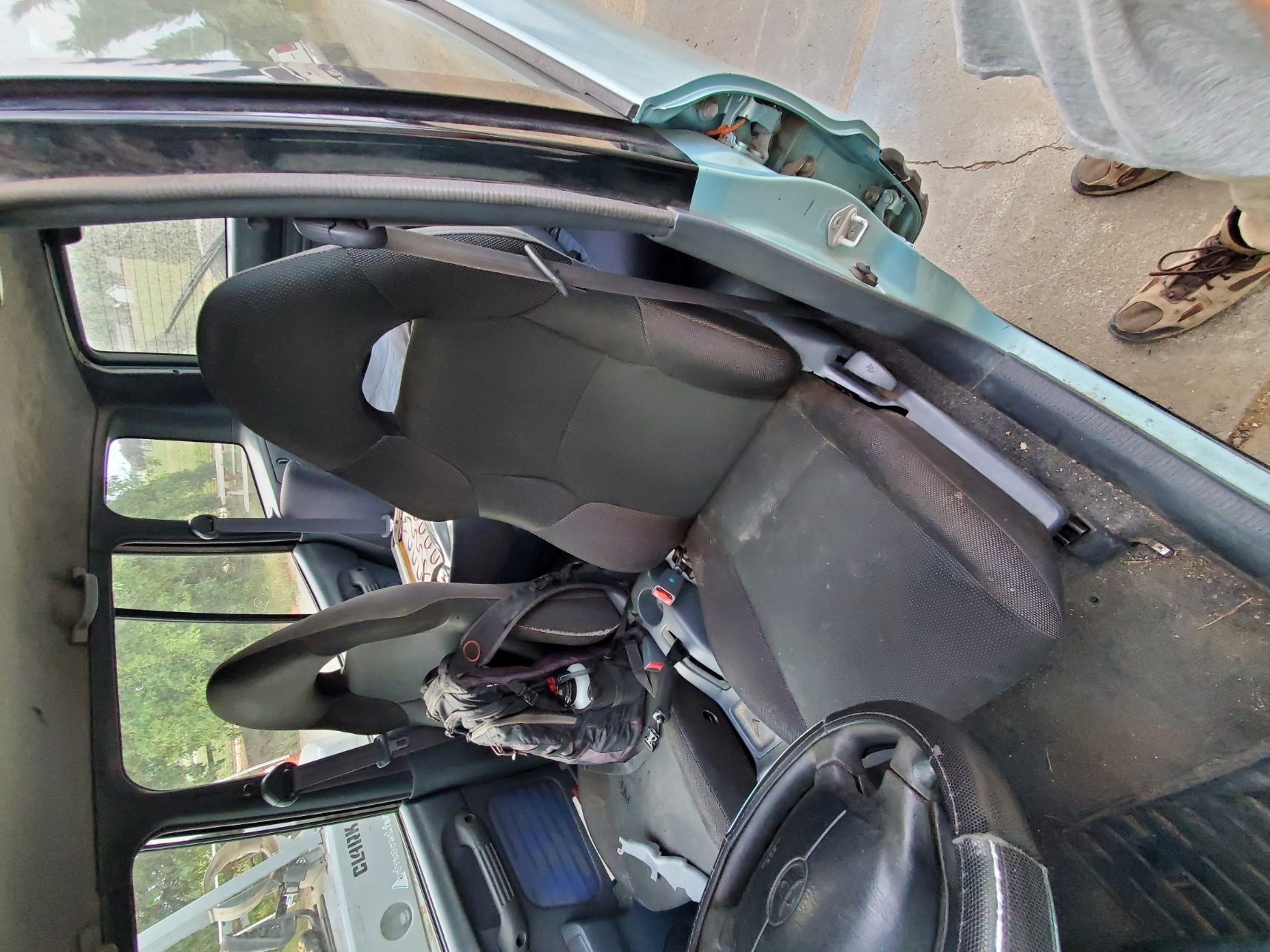
The purpose of this project was two-fold. First, to replace the decrepit front seats in my '97 RAV4. These seats would not only be in better condition, but they would also be more supportive in the turns and comfortable for road trips. Second, it was an excuse to experiment with Photogrammetry and 3D meshing as an engineering tool!
Background
Photogrammetry is the process of generating a 3D model from hundreds of still images. for a more detailed description, check out Artec 3D's article. While often used by 3D graphics artists and game designers, this tool could be used locate hard to measure features on parts or allow smooth curves to be matched in CAD. This could be very helpful for reverse engineering or retrofitting. But how easy is it to use? And can it provide the dimensional accuracy necessary for this kind of work? I would soon find out! (spoiler alert: it can do alright, but there are often better ways).
Design and 3D Model
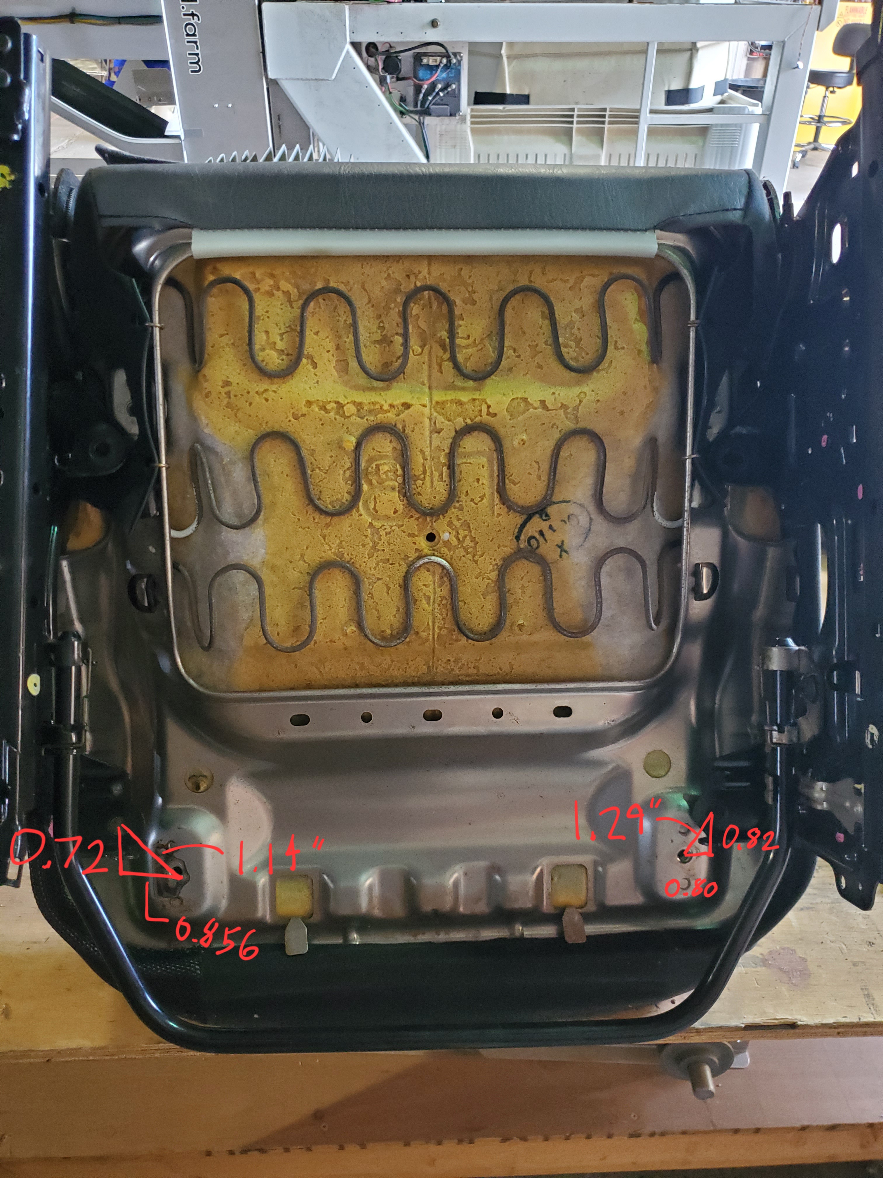
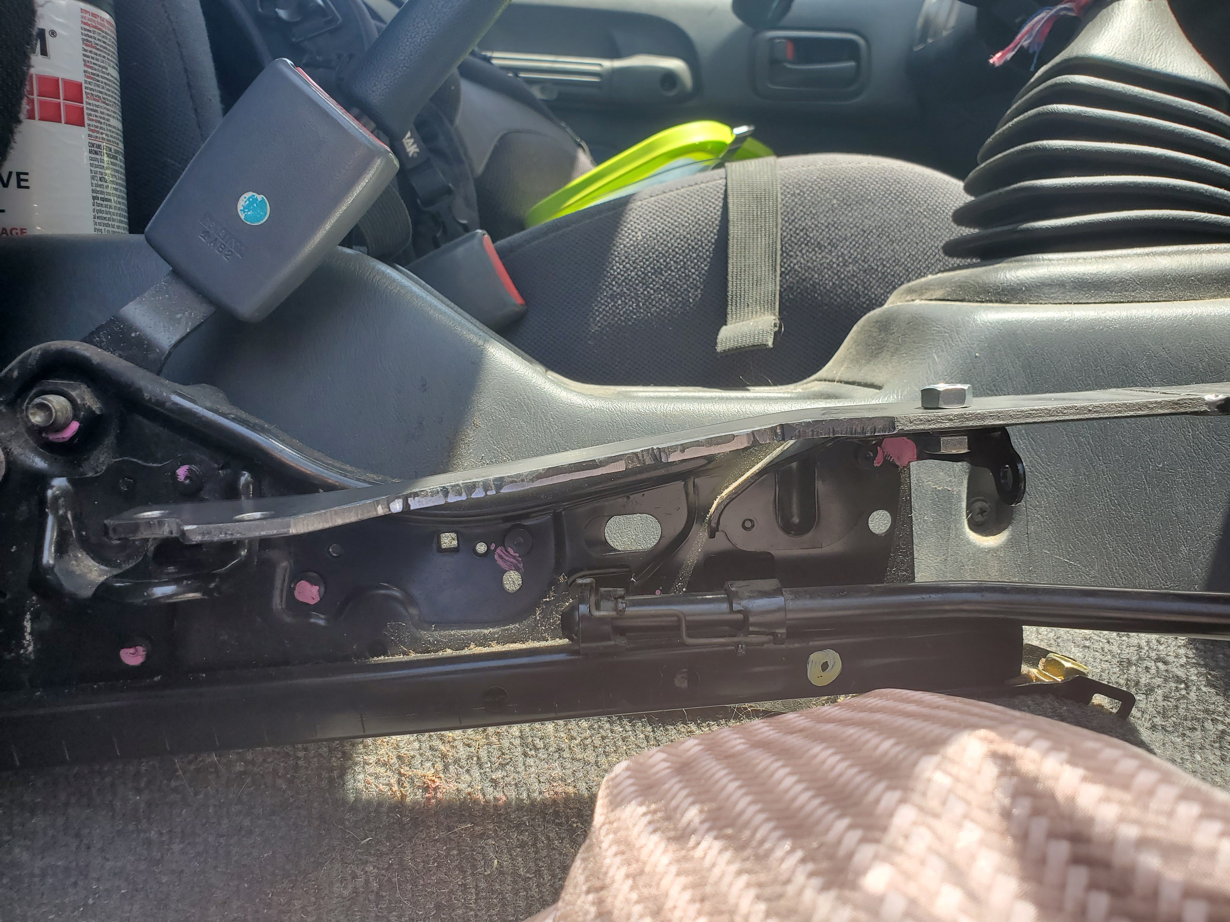
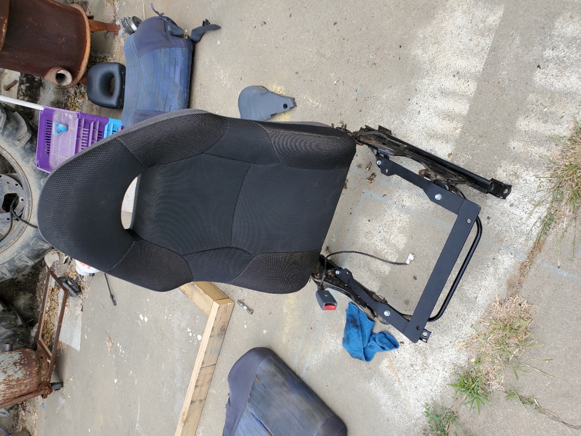
The donor for these seats was a 2001 Toyota Celica GT I found at a local junkyard with about 180k miles. 4 years newer and 126k miles younger, these seats were in much better shape than my old ones! The RAV4 has a unique floorpan with a large driveshaft tunnel for the AWD variants. This, as well as the higher seating position, made it impossible to reuse the Celica seat rails. Instead, I decided to swap the Celica cushions and seat backs onto the RAV4 seat rails. Thanks to Toyota's consistent design philosophy, the seat back bolted right up. The seat bottom was a different story. Looking from the below, the bolt holes were close, but needed an adapter to fit properly.
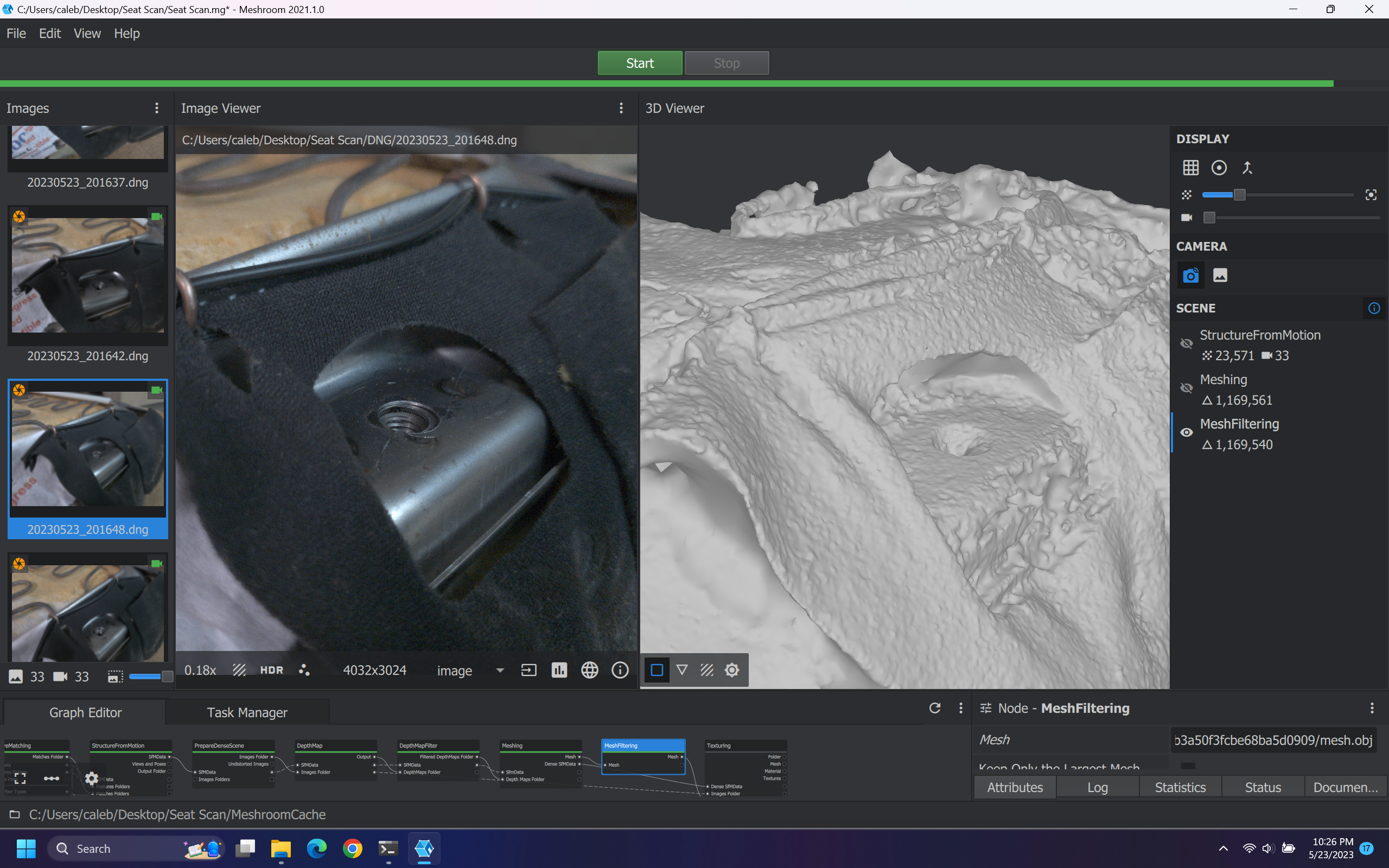
I started by taking a few photos of one of the bolt holes on the seat bottom as a test. From past experiments, I knew the shiny metal would be hard to capture, but I wanted to make sure. I was using the manual setting on my old Samsung Galaxy S10 camera saving .DNG files to minimize compression artifacts. To process the photos, I used Meshroom, a free, open-source solution to photogrammetry. It's really versatile, way beyond what I've explored! I was happy with the detail on the cloth here, but it definitely had some trouble with the shiny surface.
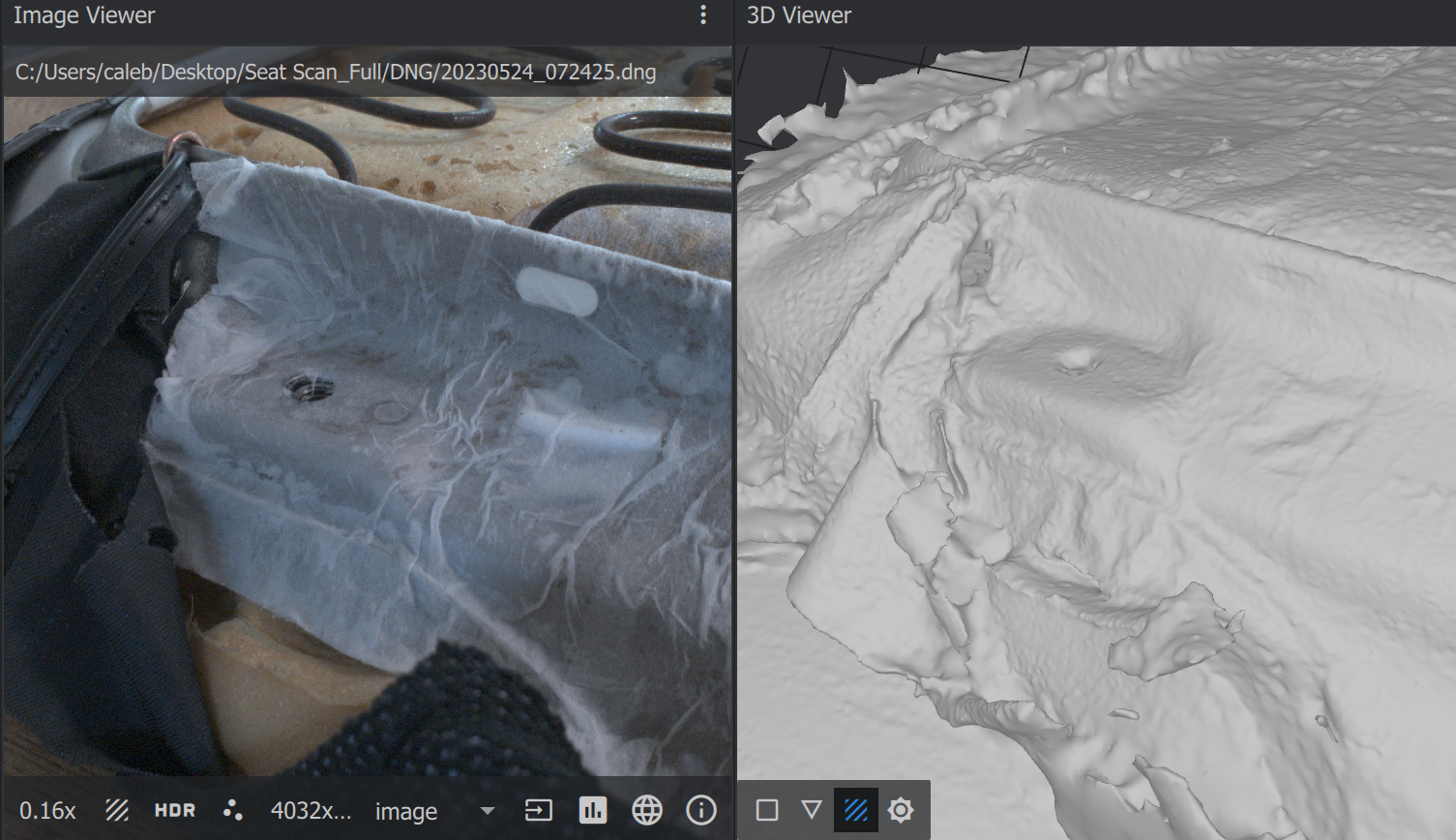
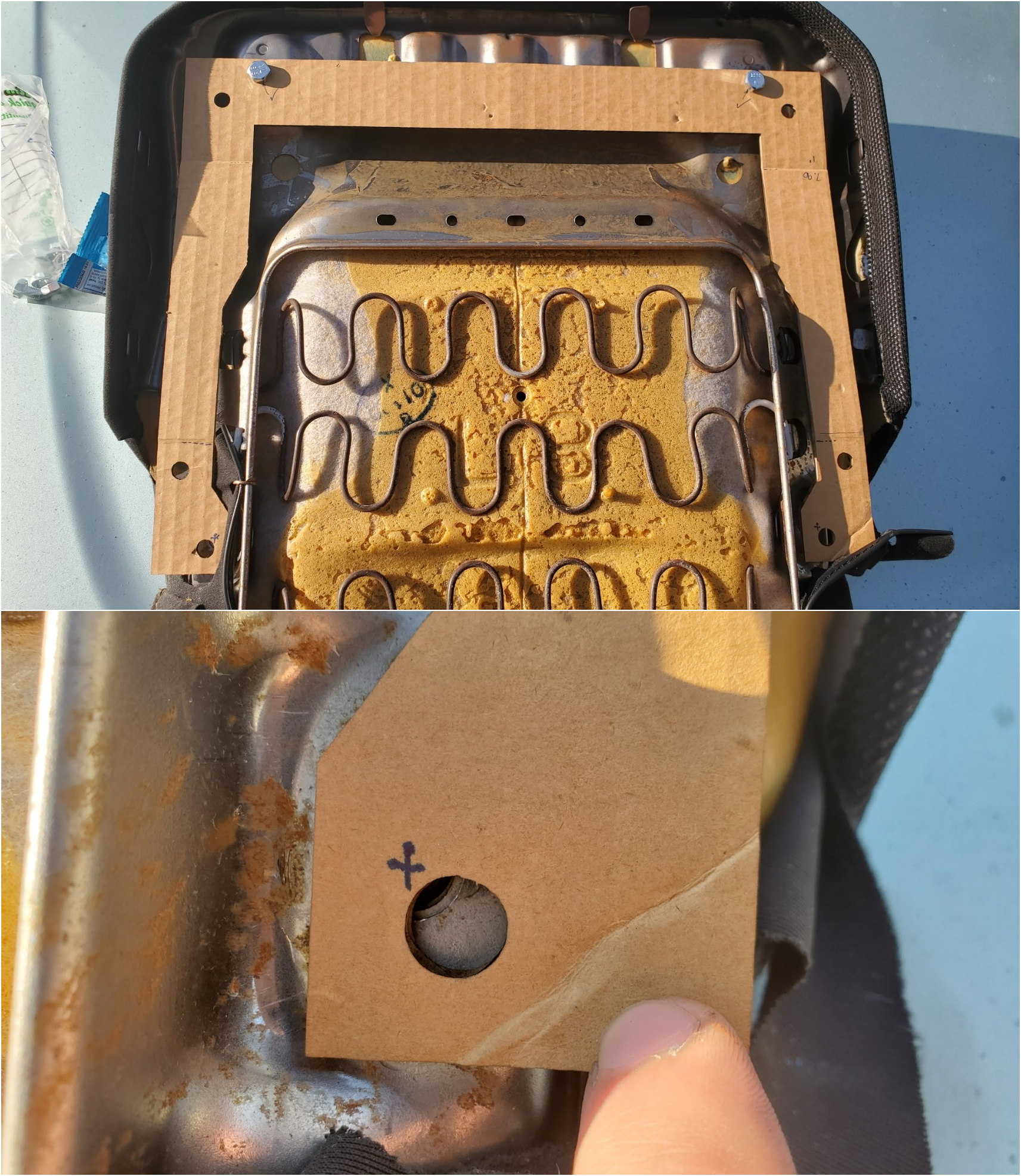
To eliminate the shine, I draped some soaked newspaper or toilet paper over the metal parts, cutting holes for the bolt locations. In hindsight, I would have liked to use a dust or powder for better coverage around critical features. Commercial scanning sprays are available, but I've heard a little flour or baby powder can also be effective. Nevertheless, the paper gave decent results.
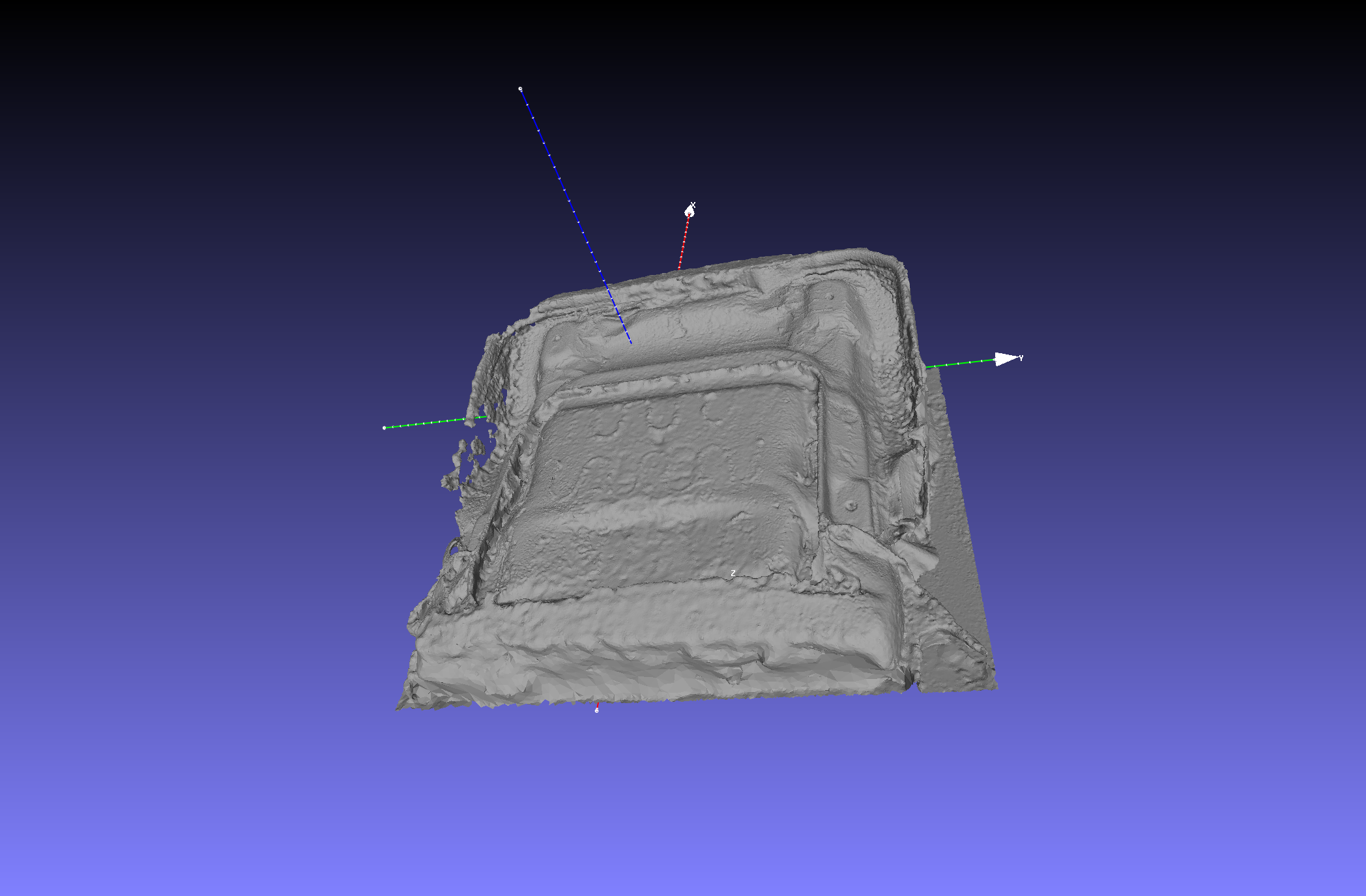
Meshroom can produce a model, but that model isn't very useable yet. With the model imported into Meshlab (another free program), you can see it isn't oriented properly at all. What's more, it isn't scaled properly and it contains nearly 3.5 million faces - way too much detail for even my gaming laptop!
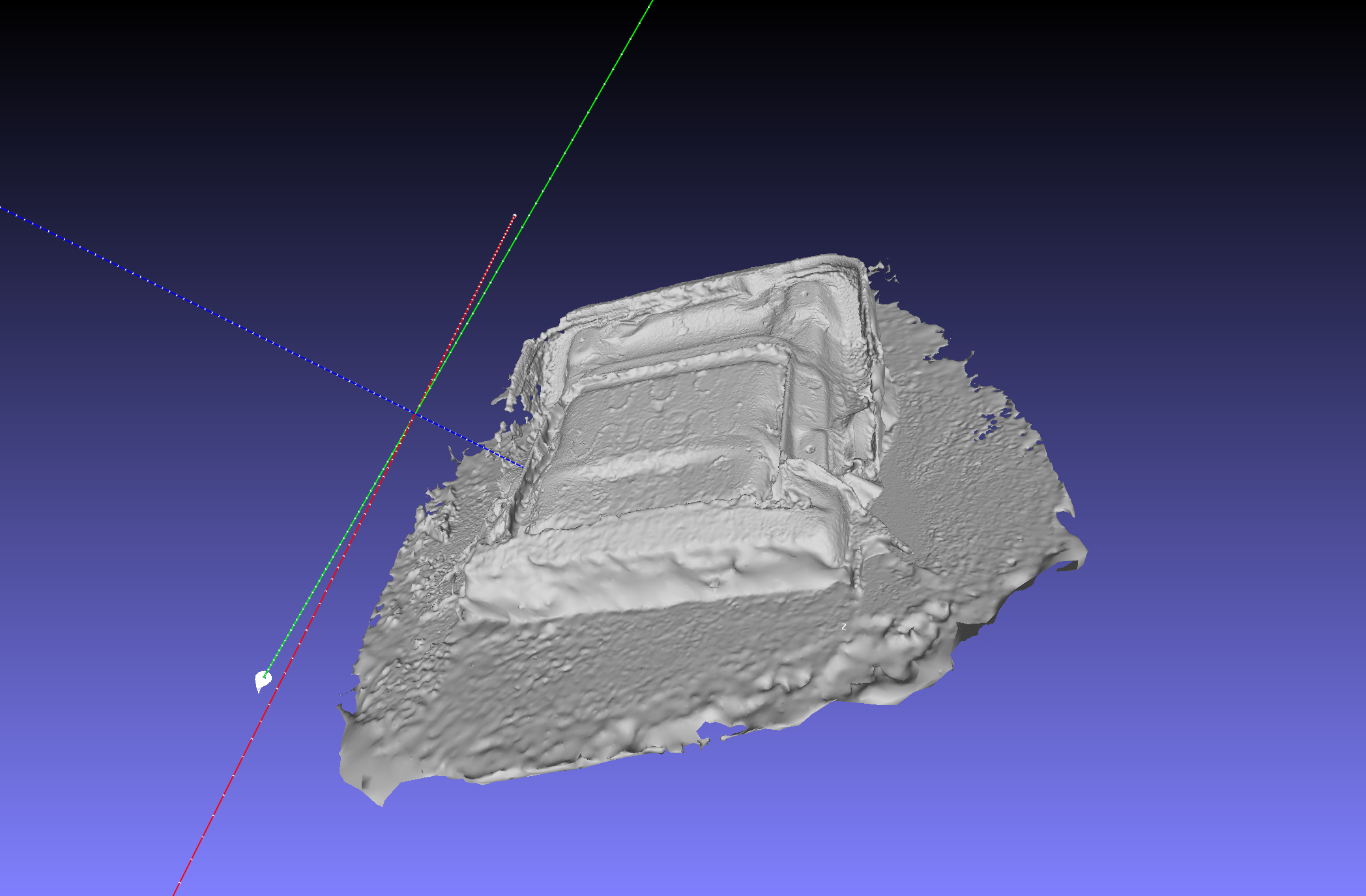
Meshlab is great at handling huge meshes like this. The first thing to do was scale the model properly. I did this by measuring between distinct features on the model and in real life, then calculating a scaling factor to correct for the difference. I regret not including an easily scannable object of known size for this purpose, as my tape measure was probably not giving me the most accurate measurements! Next, I oriented the model to the XYZ axes using the bolt mount planes and the flat sides as reference. Meshlab has tools to do this by averaging the position of a number of selected points, which did fairly well, but wasn't perfect. Finally, I trimmed away the flat table surface and any floating geometry, then scaled down the detail on all the non-critical features using the 'Decimate' function. This brought the number of faces down to 1.75 million - still far to many in hindsight, but certainly more manageable.
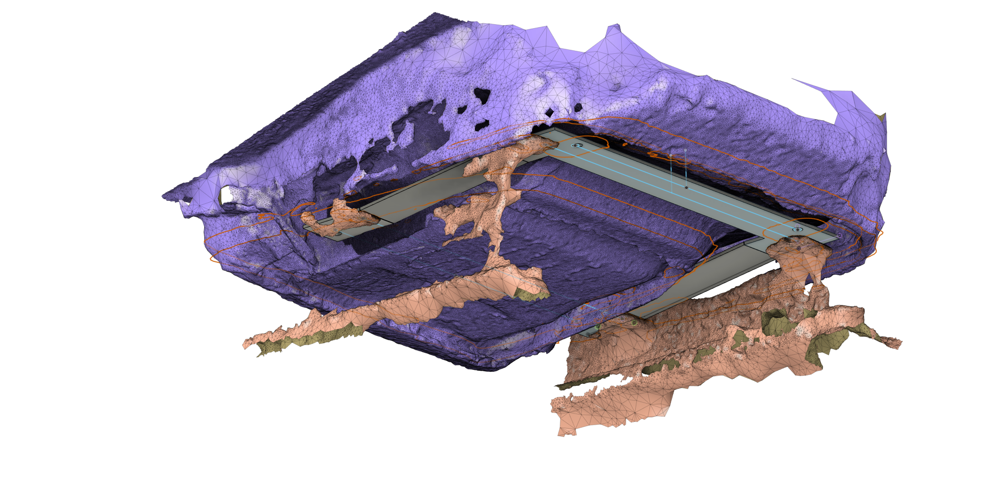
I repeated the same process for the seat rails, this time focusing only on the rails themselves and erasing everything else. Then I imported these models into Fusion 360. Aligning and joining these models turned out to be very challenging since there were not real flat faces to work with. I made a few reference planes, one for each set of bolt points (grouping front and back), but even these weren't exactly parallel since each one was just defined from 3 points on the mesh.
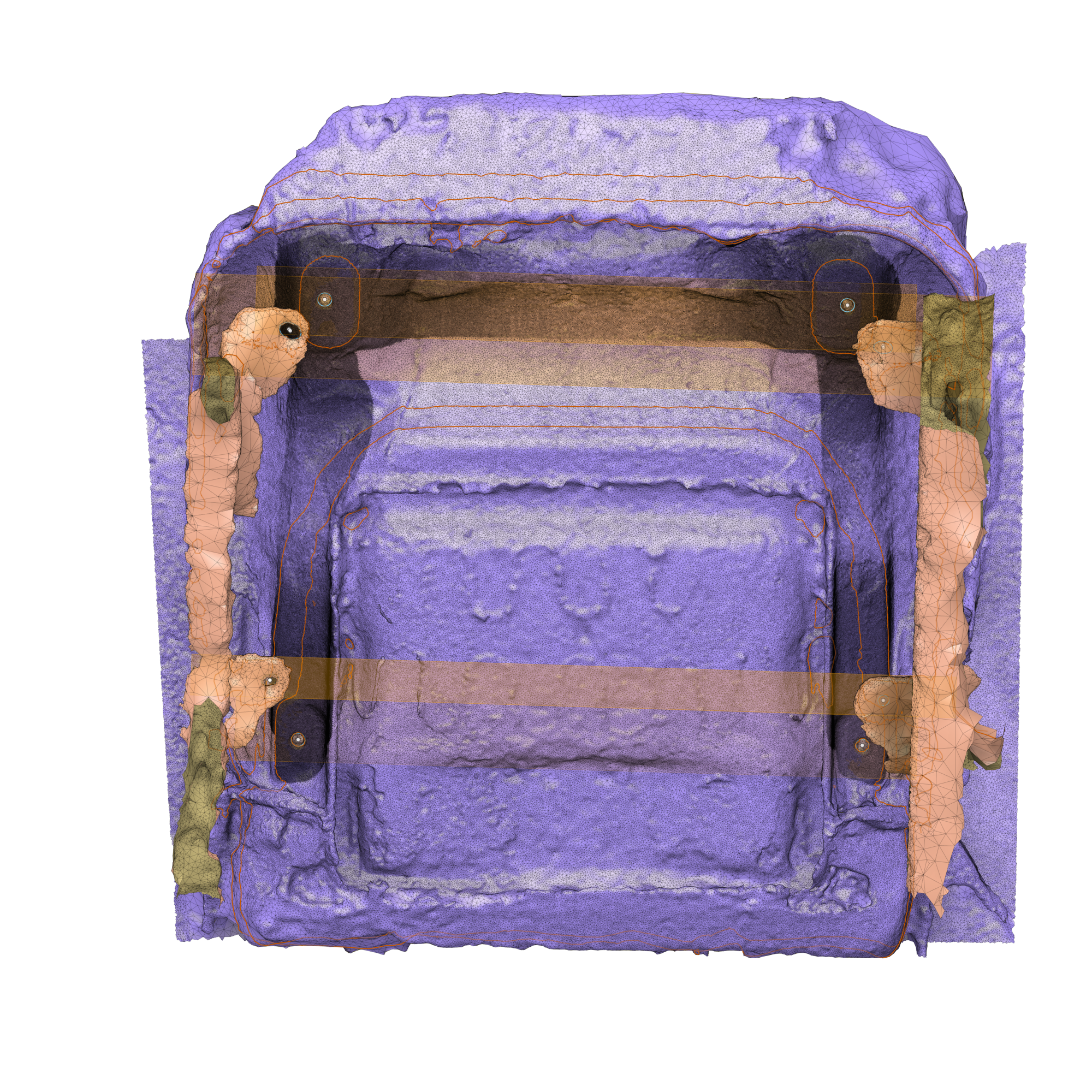
Finally, I could draw up an adapter. The design was simple, with the holes being located by Fusion's sketch-from-mesh feature.
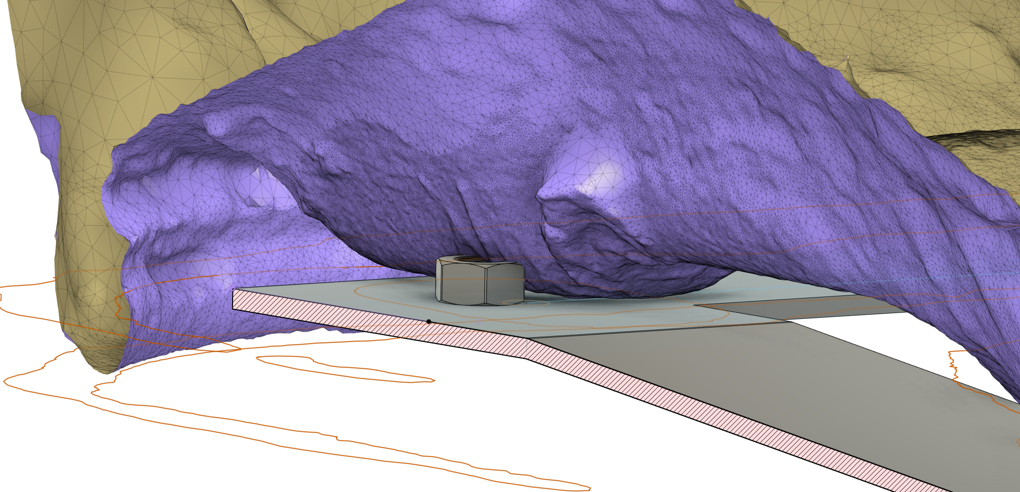
One advantage to designing this way is the ability to foresee clearance issues with a digital cutaway. Here, the nut receiving the bolt from the seat rails is shown interfering with the seat cushion. In real life, this would have been hard to see since the seat cushion comes down around this area and blocks your view.
Before settling on a final design, I iterated through two laser-cut cardboard versions. The first highlighted some problems with my model and the way some sketches were projecting. Scaling the seat rail model down by 98.63% and fixing those sketches helped a lot.
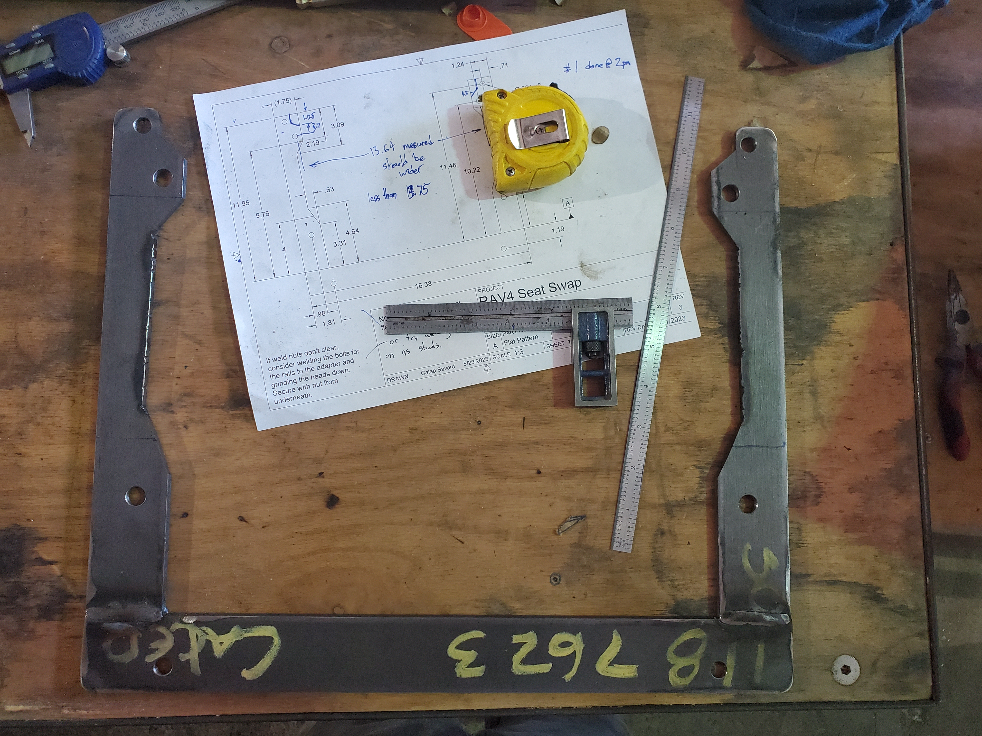
The second version fit the bolt holes, but as I tried to install the seat bottom on the rails, I realized that it located the seat bottom about 3 inches too far backward and that it was interfering with the seat back. After updating that, I bought some steel flat bar and got to work!
Fabrication
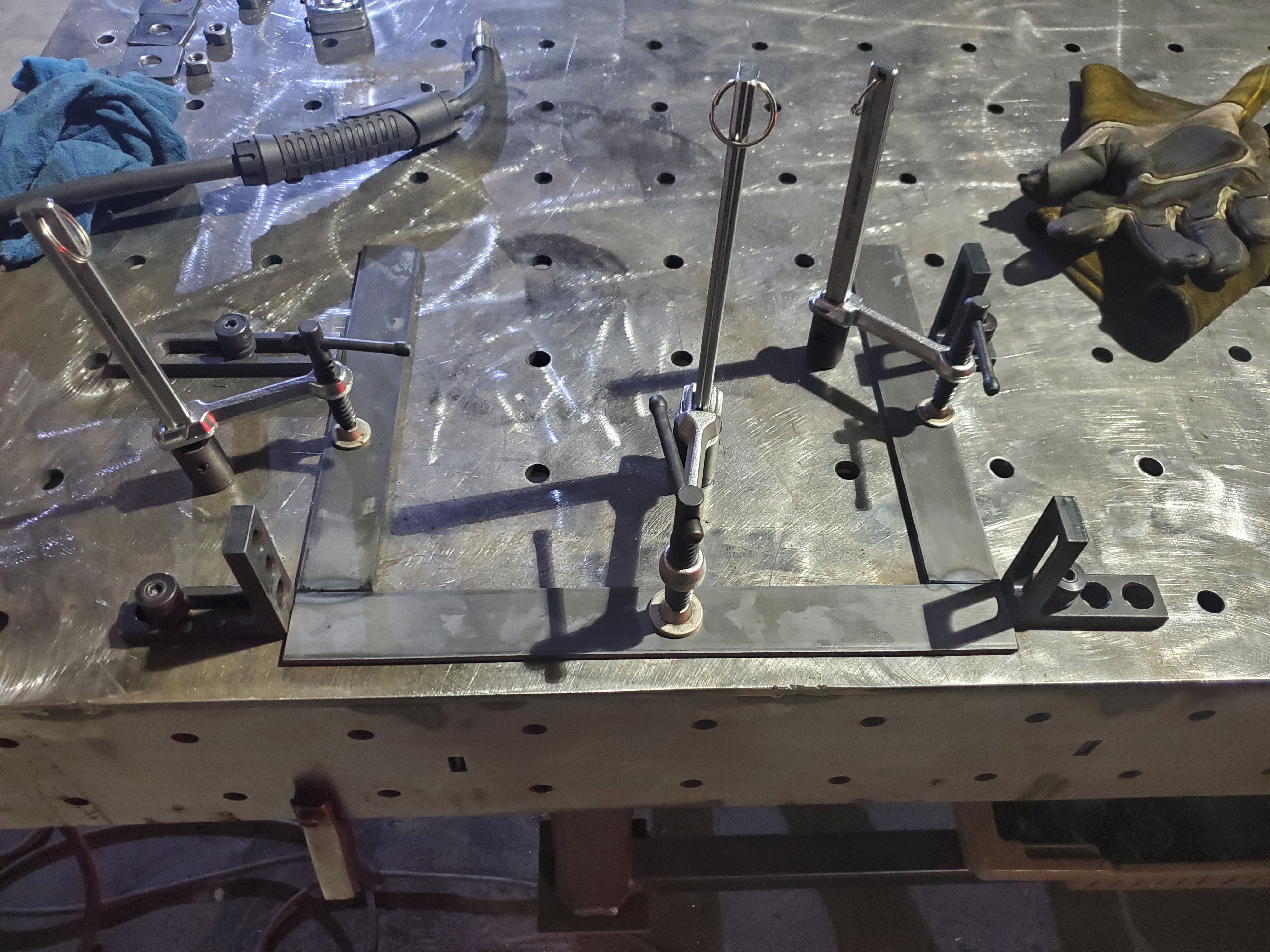
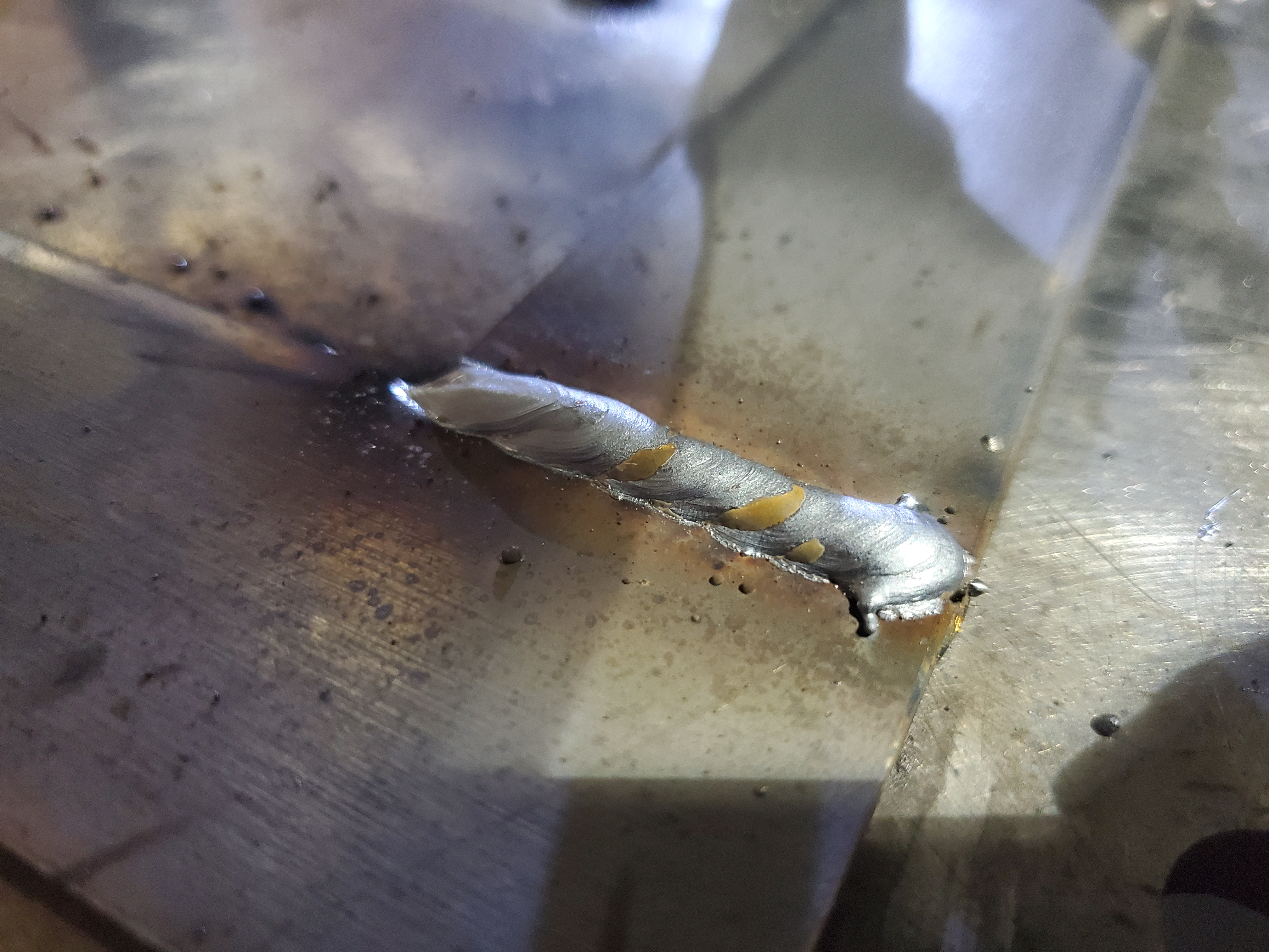
Building these brackets took me a lot longer than I expected! 4.5 hrs for the first one and 2.25 hrs for the second. I enjoyed getting to spend a Saturday in the shop, but it probably would have been worth it to outsource this to someone with a fiber laser. I made it out of 3/16" x 1.75" flat steel because 1/8" stock was not available. Needless to say, it's beefy!
Conclusion
After using photogrammetry in a real project, I can see it has some clear advantages and disadvantages.
Advantages
Accessibility - All I needed was a smartphone and a computer. More computing power definitely helps though!
Captures 3D space well - For complex 3D curves or surfaces, I dont think there is an affordable substitute.
Accuracy - It's hard to tell which problems were from my fabrication techniques and which were from the photogrammetry process, but all the measurements I made on the model seemed to be within about 1/16” of the truth. I'm sure this could be improved with better photogrammetry procedures, but for this project, that's plenty!
Disadvantages
Time consuming - Taking all the photos, generating the model, cleaning up the model all takes a lot of time, and all that has to happen before you can even get the model into CAD. If you realize something is wrong at that point, you might have to start over.
Surface-dependent - If a surface is shiny or transparent, it has to be prepared, which is also time consuming.
Lighting-dependent - If you don't have studio lighting, you have to wait for the sun or the clouds to cooperate.
Resource intensive - - CAD with large meshes can require serious computing power.
If I were to do this again, I would be sure to add something with sharp edges to the scanning area for scale. I would also leave the bolts in the holes during scanning since the bolts would likely scan better than the dark internal threads. Finally, I would spend a little more time preparing the surface for scanning, using a powder or dust instead of the soaked paper to get better detail on the features that mattered.
In the case of this project, a few hours with some cardboard and a box knife could have probably produced similar results. However, for more complex parts, photogrammetry could be worth all the effort. In the end, photogrammetry is the poor man's laser scanning, and it trades up-front cost for backend labor. As a hobbyist without an engineering department budget, I will keep photogrammetry in my arsenal, but only for projects that really need it.
For anyone looking to recreate the project, I've included some build files below. I would recommend having the adapters made by Send-Cut-Send or Fabworks (or any of the other online fabricators), even if you have your own machine shop. Laser cutting is just way easier and more accurate than cutting, welding, and drilling flat bar. I can't guarantee that you'll get a fitting part since I built mine by hand and could have made some fabrication errors, but if it doesn't fit, please let me know so I can update the drawing!