


Skills Showcased
For my senior design project, I worked with a team of 3 others to design, build, and test this device for removing asphalt particles from a shingle production line for our sponsor GAF. At the end of the year-long project, we had determined that brushing was an effective method of removing these particles, succeeding in removing over 80% of them. We were also able to deliver recommendations on bristle type and future testing.
Background
In manufacturing their shingles, GAF applies a coating of asphalt particles called fines.
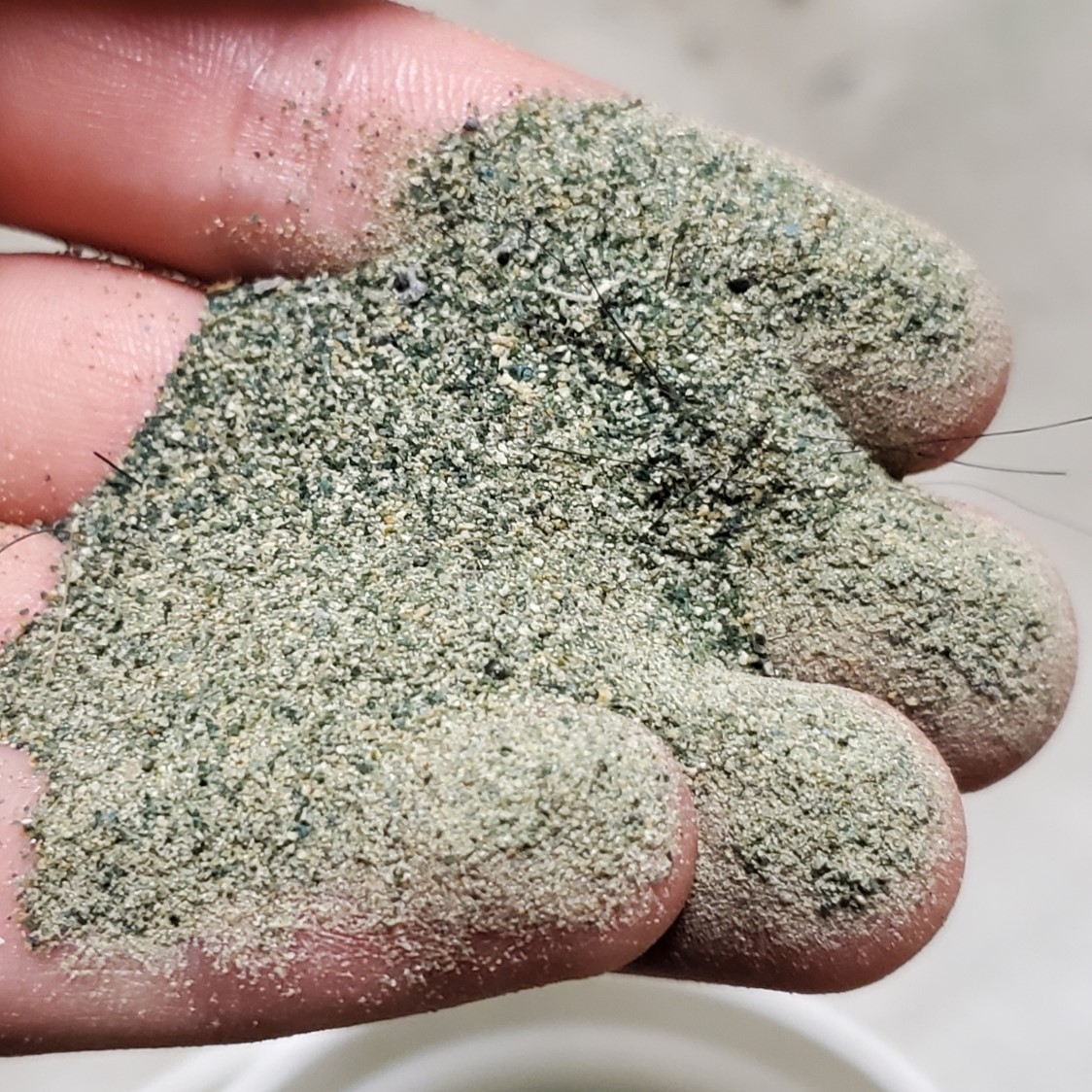
Most of these fines stick to the shingle, but vibrations eventually cause some fines to fall off throughout the production line. This causes waste and mess, so GAF sponsored a senior project team to develop and deliver a quarter-scale prototype to solve the problem.
Ideation and Design
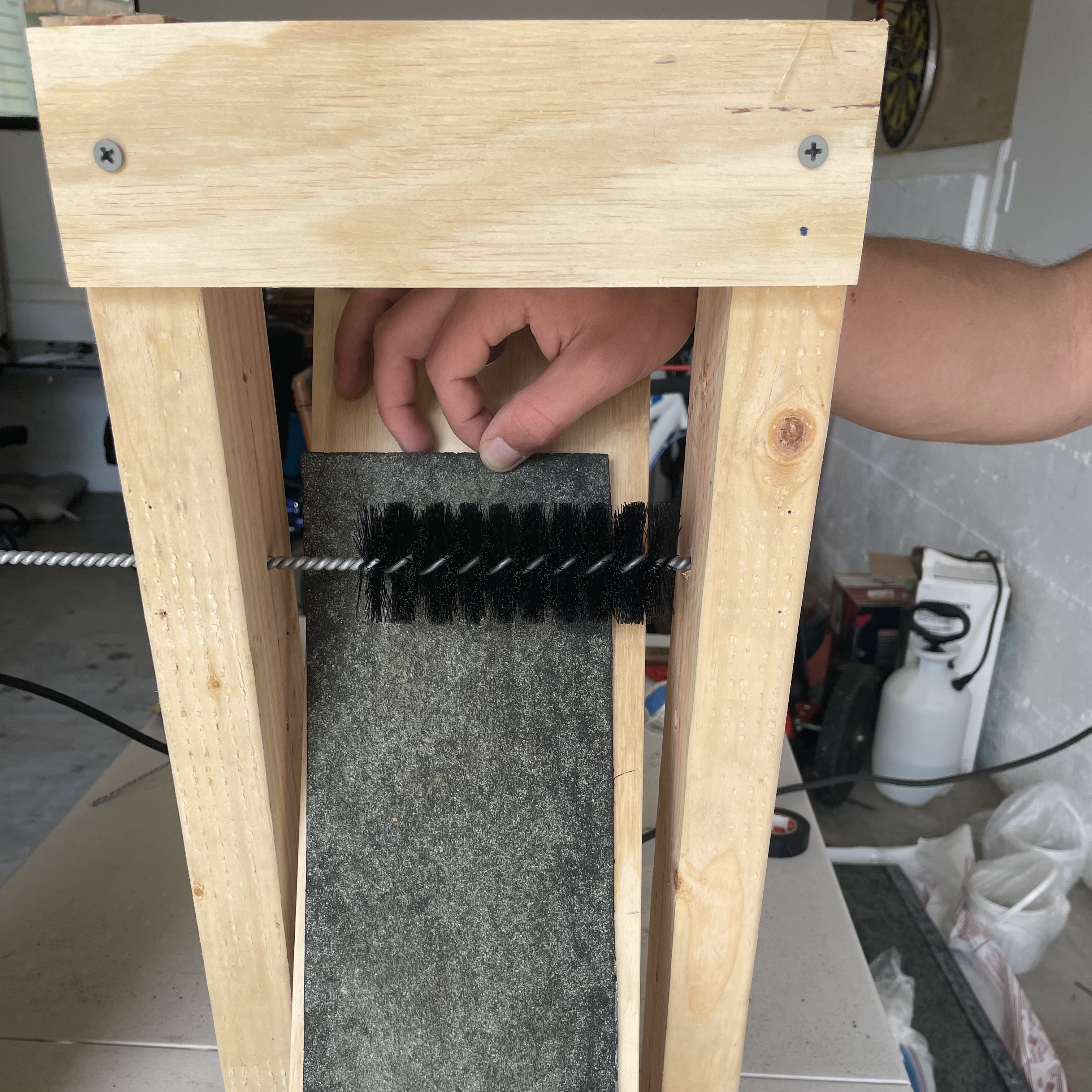
We first reduced our assignment to its component functions: removing fines from the shingle, collecting them in an organized manner, and remaining structurally stable. After researching various related devices and patents, my team and I sketched several solutions we thought were viable. A weighted decision matrix was used to compare the effectiveness of each solution at accomplishing each design criteria. The design direction took the shape of a rotating brush to get fines off the shingle and into a chute. To verify the effectiveness of this design, we mocked up a concept prototype and ran a few rudimentary tests.
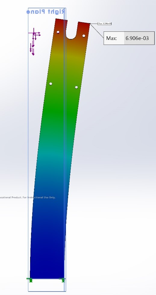
These proved promising, so we continued toward developing a final prototype. We contacted industrial brush manufacturers for bristle samples and chose the 3 most promising types. We ran hand calculations and FEA on the structure to ensure it could handle the static and vibrational loads.
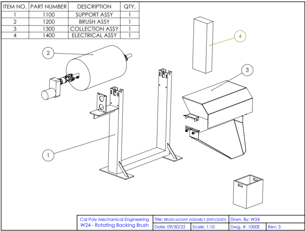
Finally, we made drawings from our CAD model and sent them off to our sponsor for approval.
Fabrication
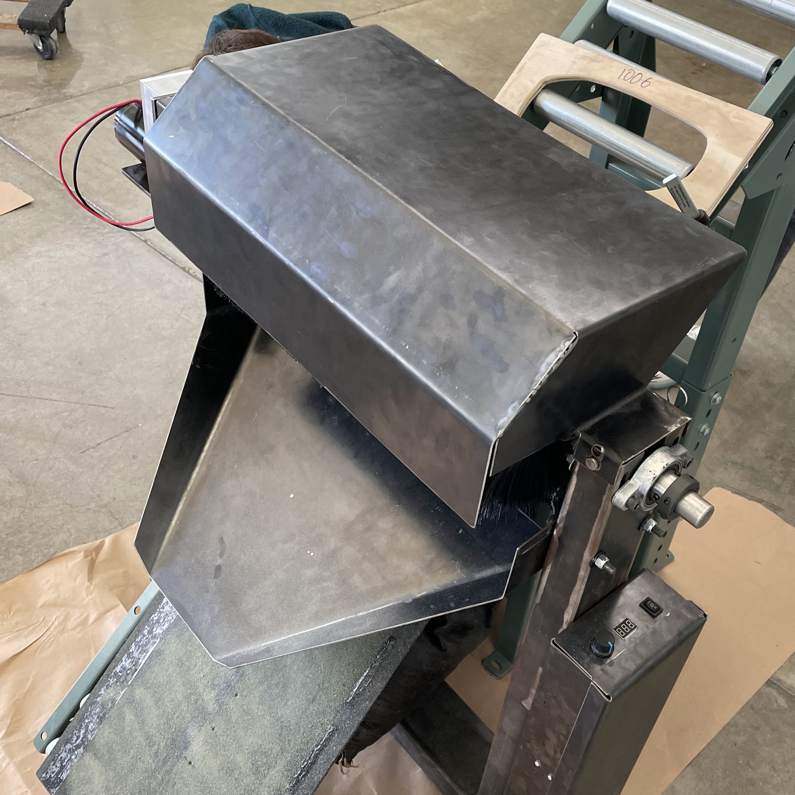
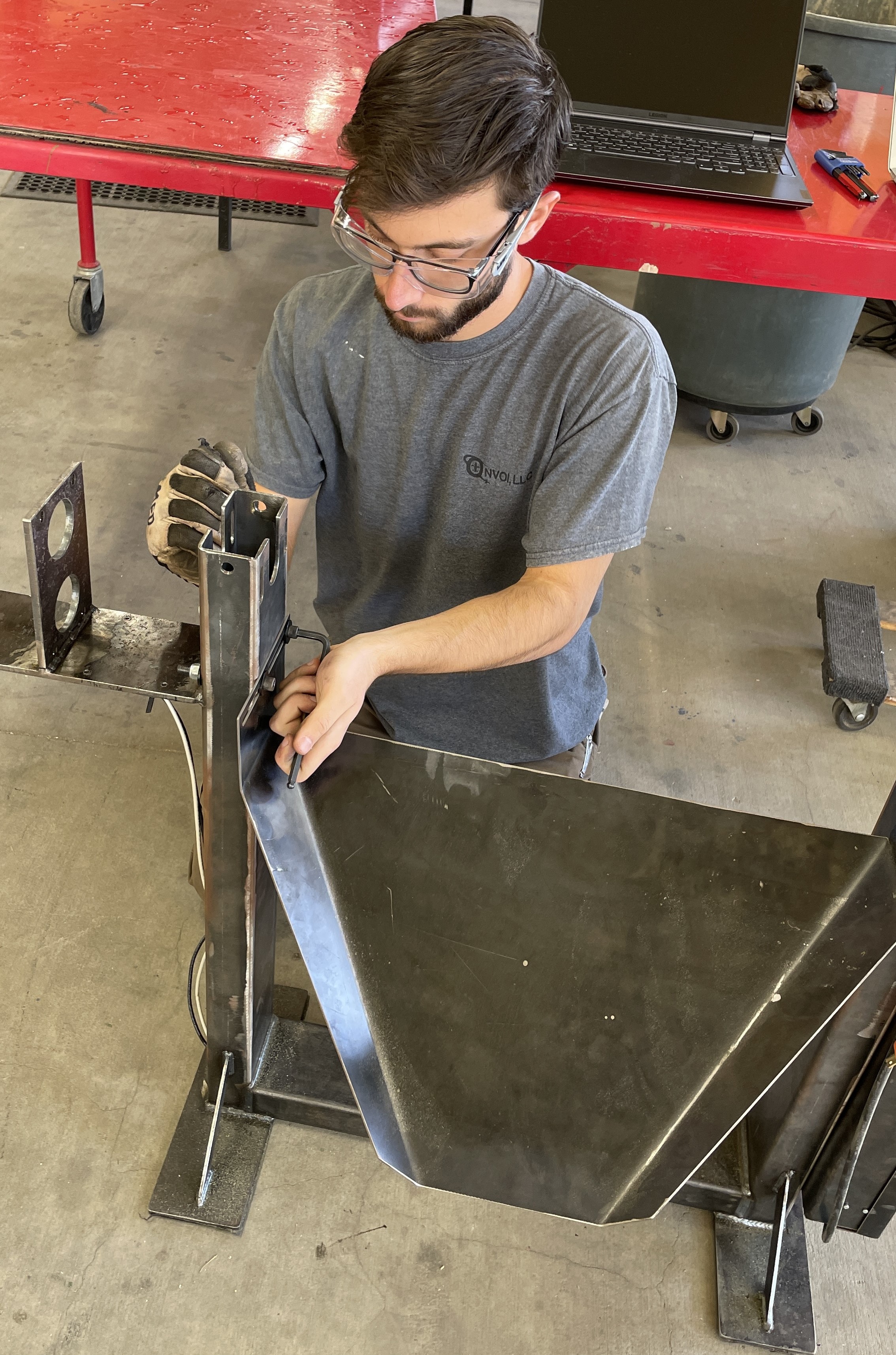
The main frame was made by GAF with minor changes to our drawings. It was our job to produce the sheet metal parts (since the school has a waterjet), the electronics, and work out any problems that arose.
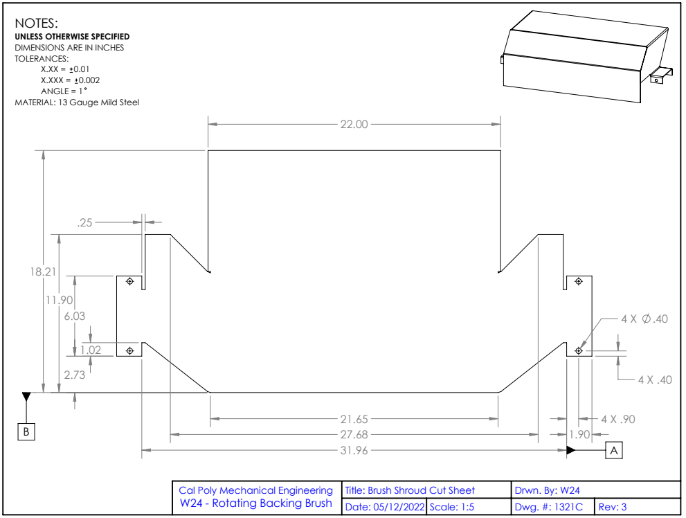
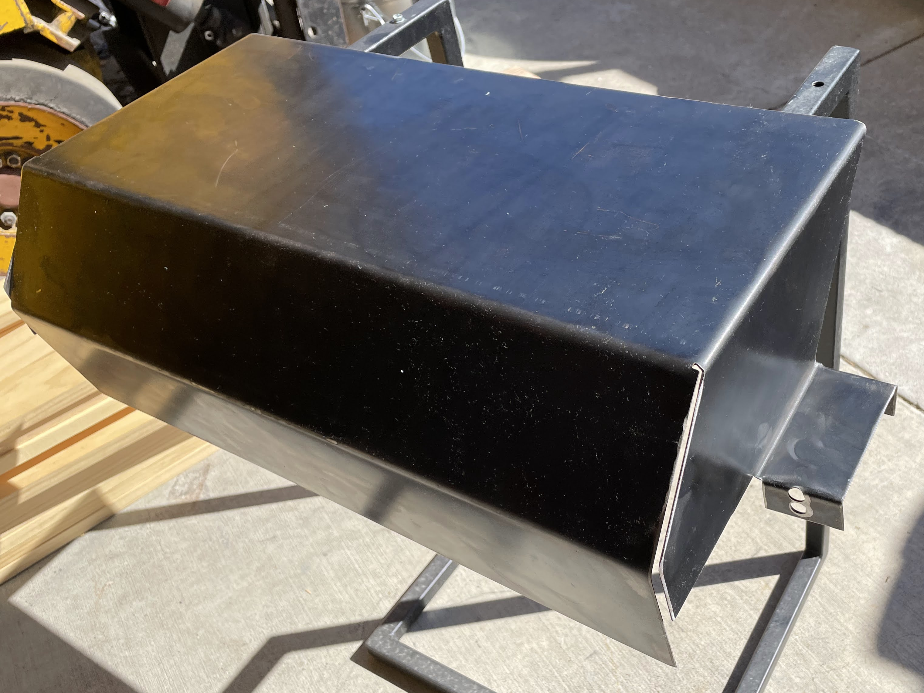
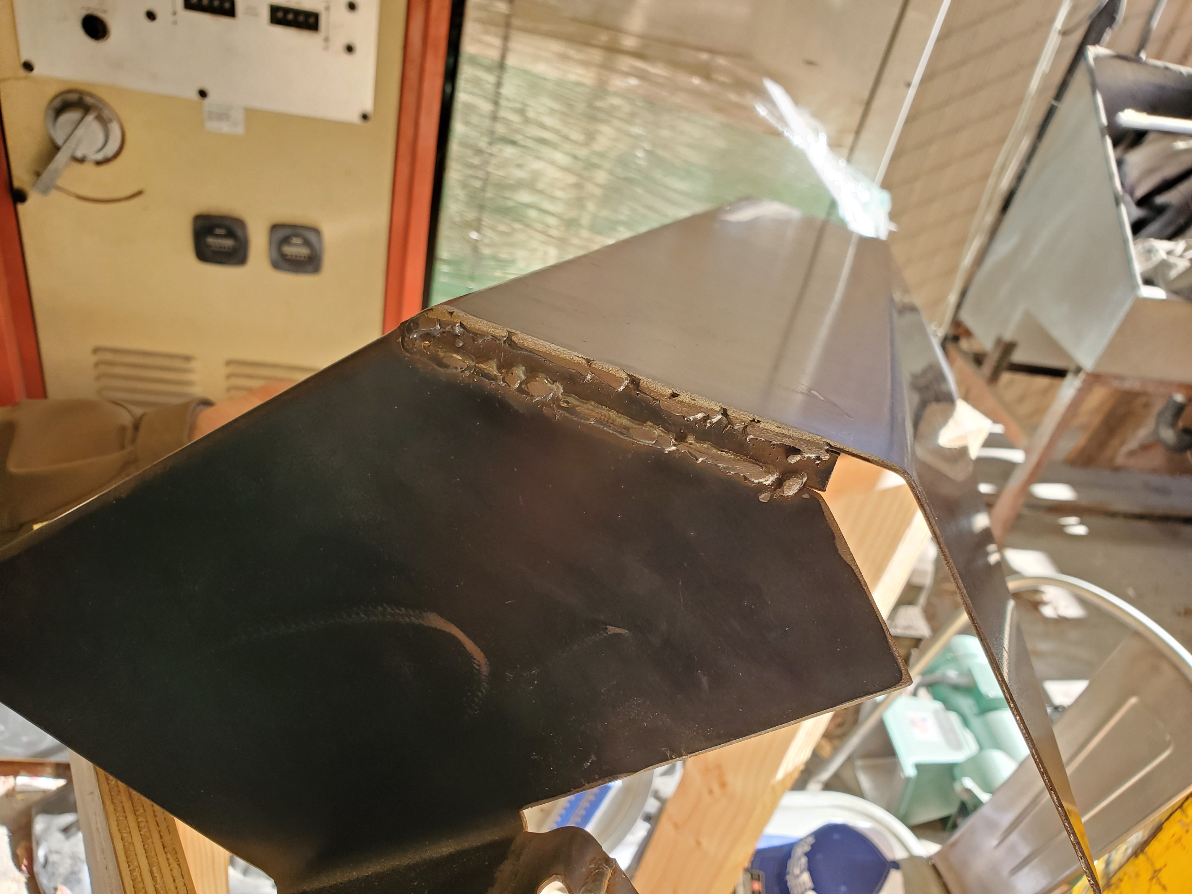
The brush shroud and chute were cut by a Cal Poly shop technician on the waterjet from our SolidWorks sheet-metal model. Next, we made the bends specified on our drawings using brake. A malfunction during cutting caused one quarter of the shroud profile to be cut about ½” too short, but we bent it as planned and welded on extra material where necessary.
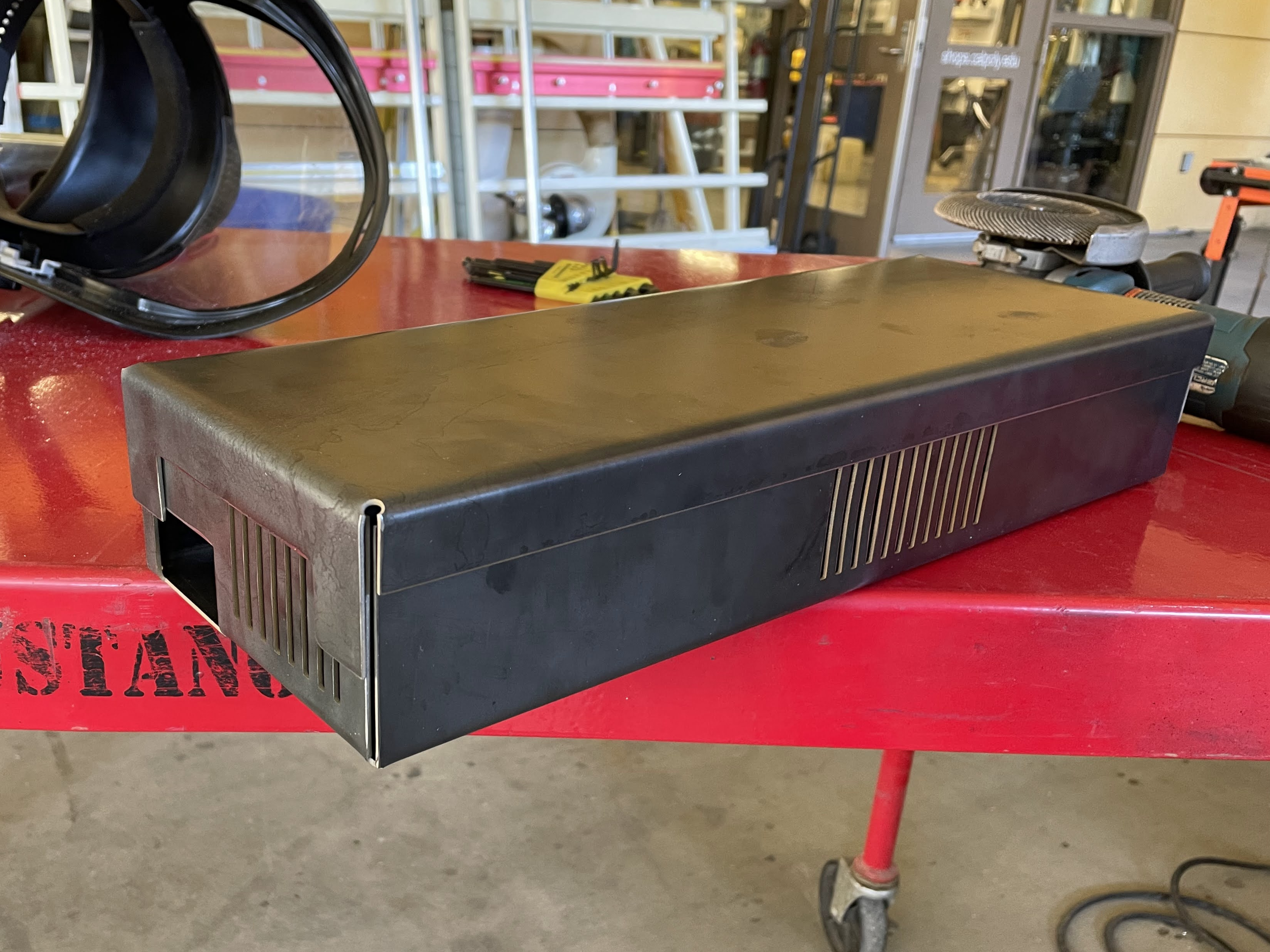
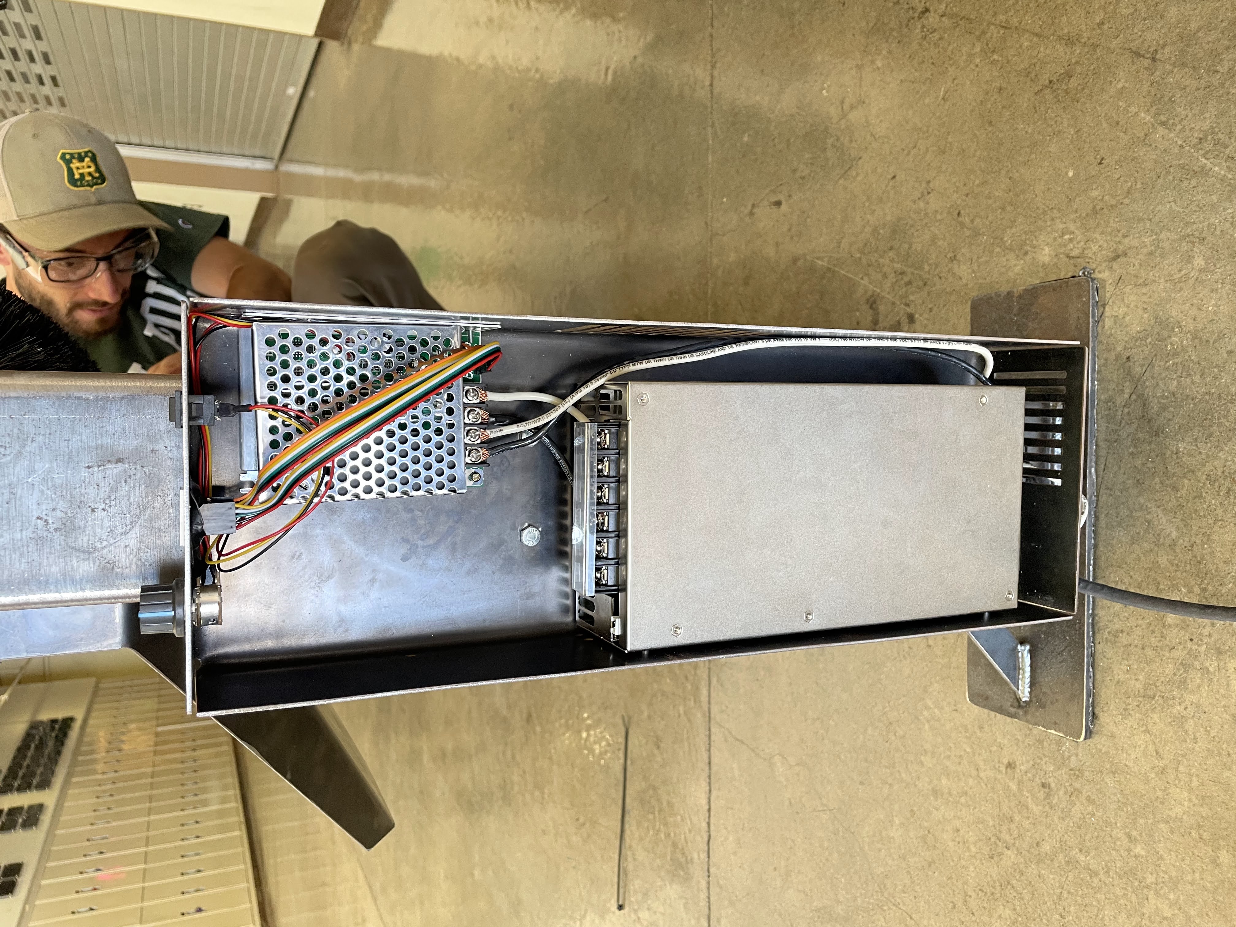
We also designed and fabricated an electrical box using the same techniques. This included vents for airflow, cutouts for controls and readouts, and a lid. Our DC power supply and motor controller would be mounted inside.
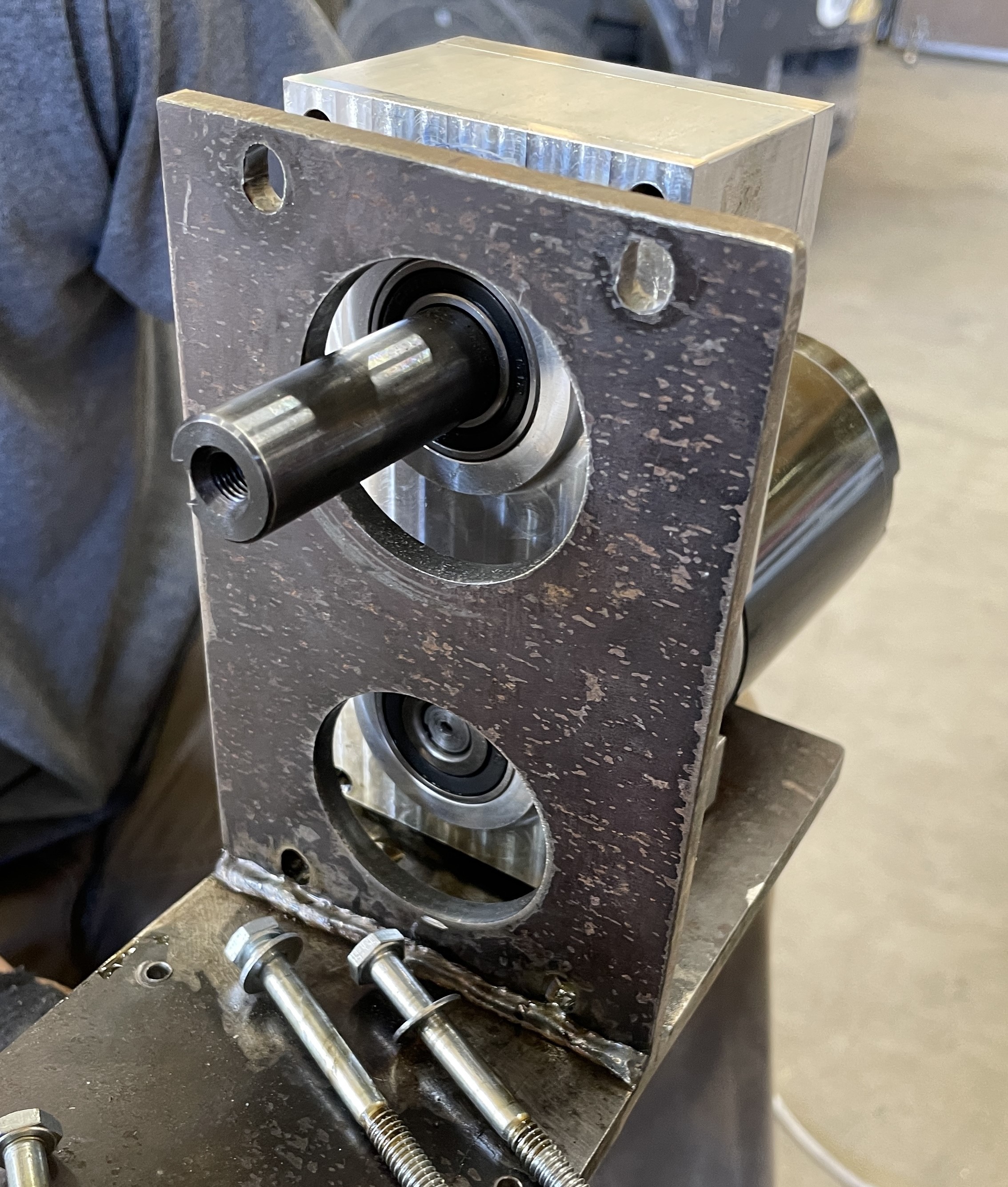
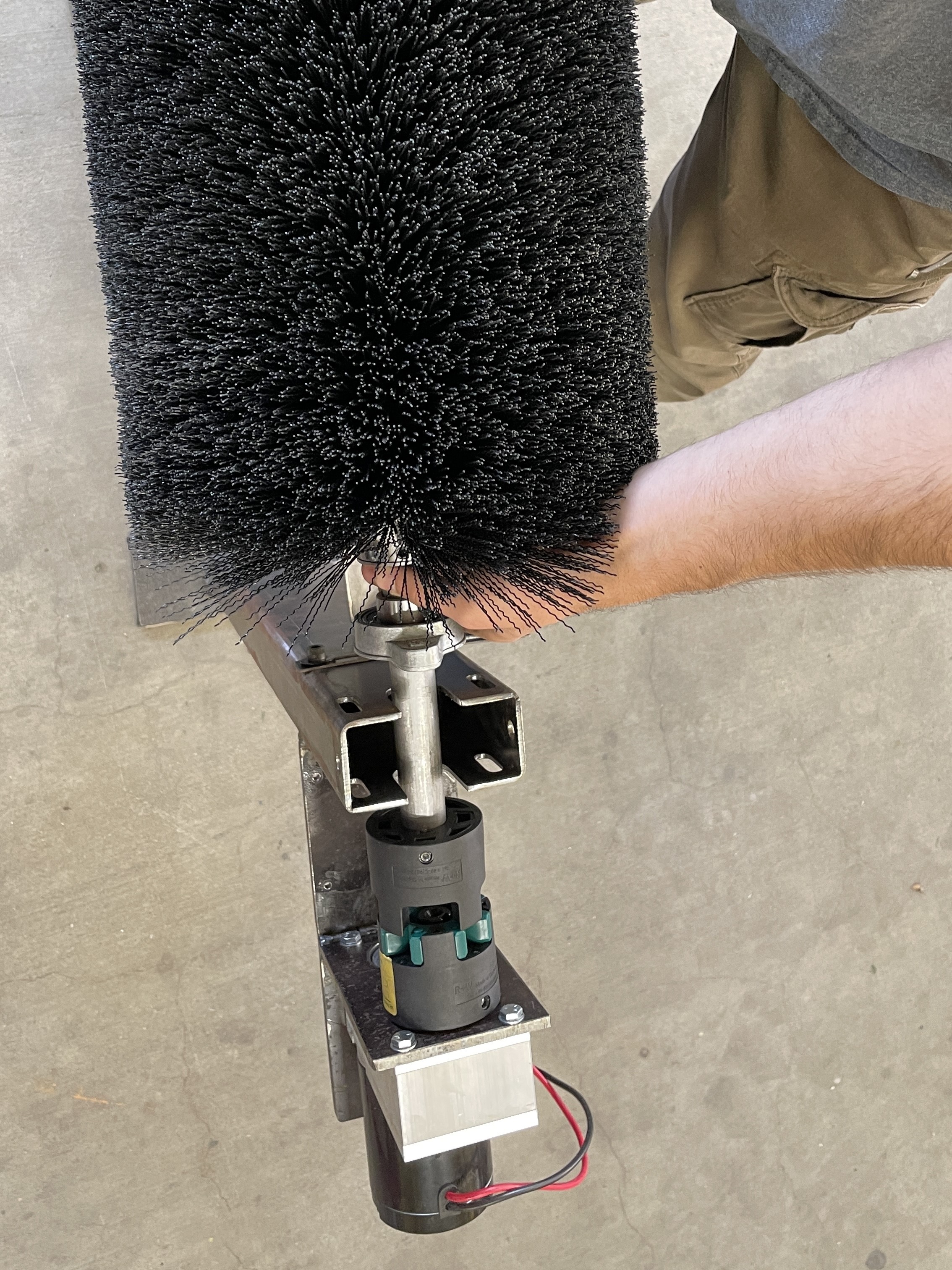
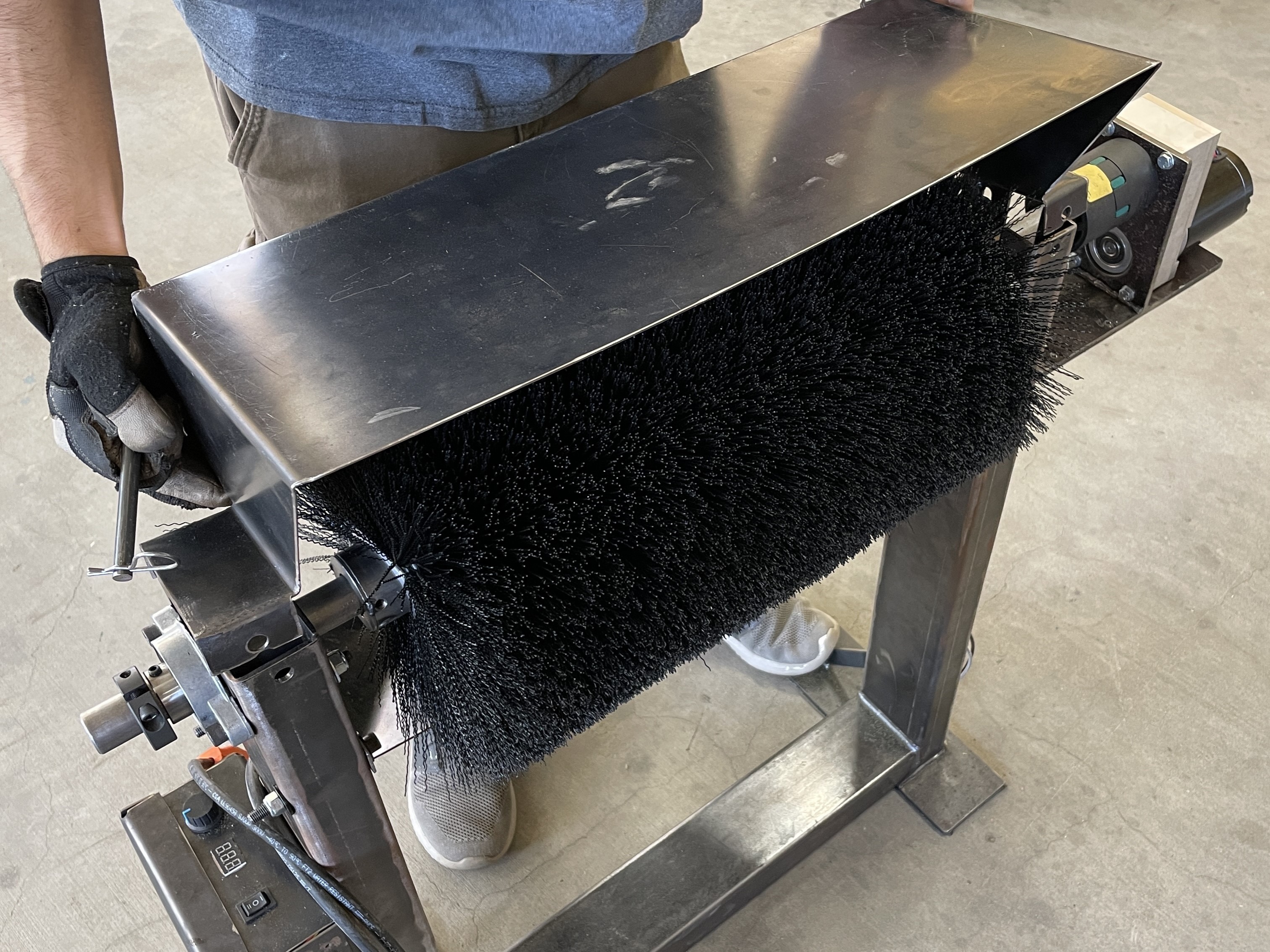
Finally, we assembled all the parts.
Testing and Results
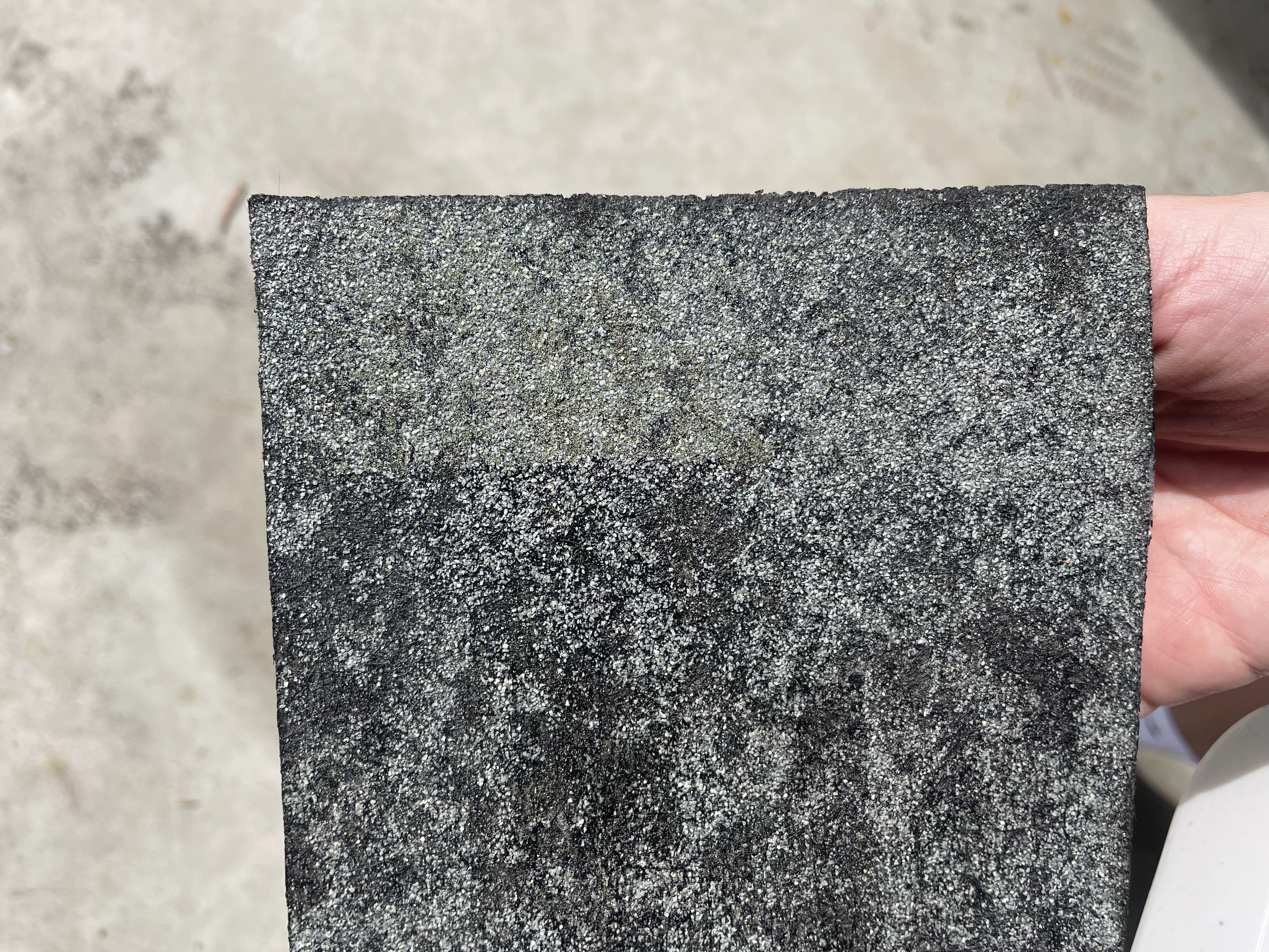
We wrote 11 test procedures to verify that the prototype met our design criteria. The most important was the Fines Removed and Collected tests, which measured how much of the loose fines were removed from the shingle, and how many made it into the collection bin.
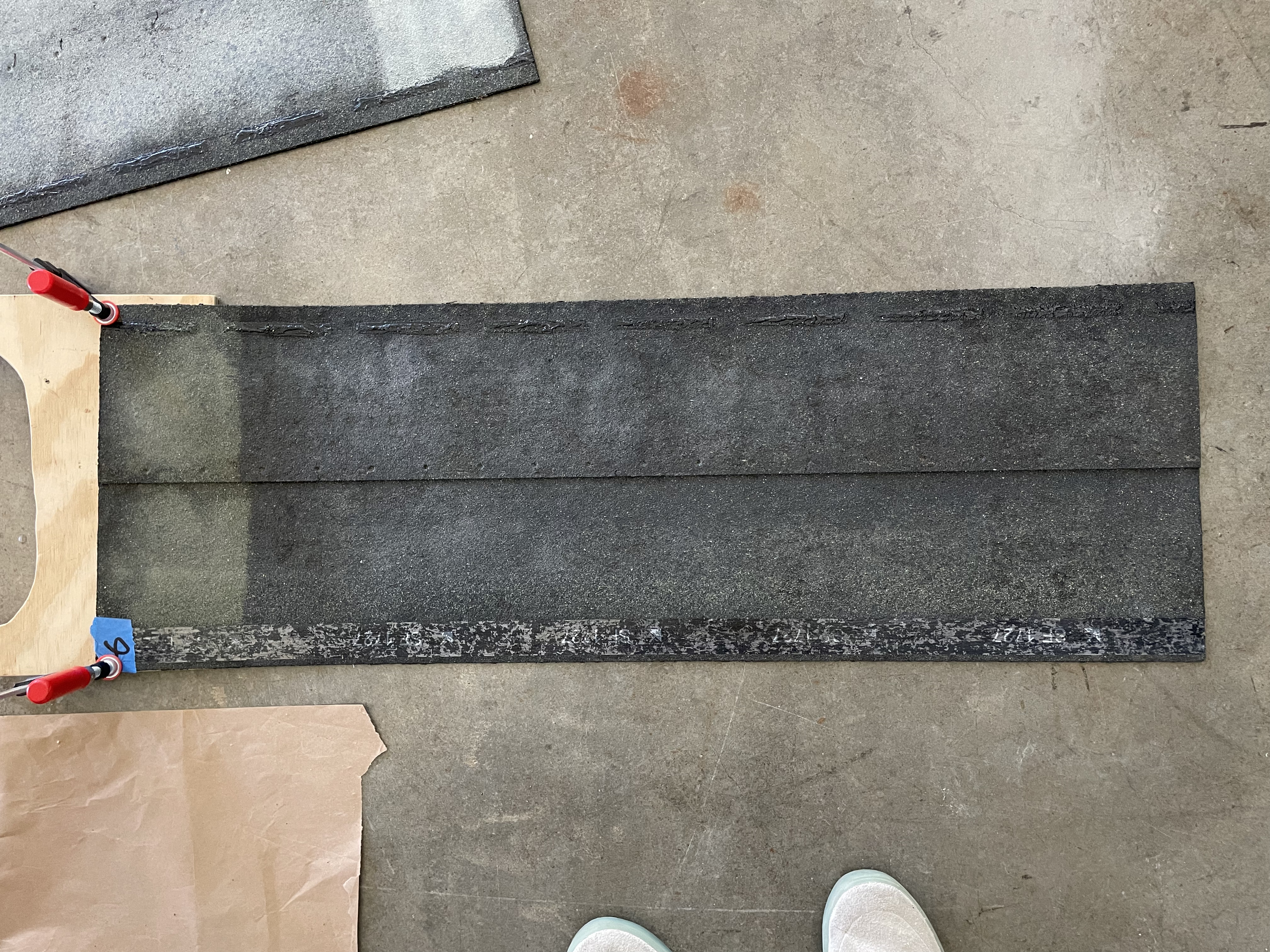
We simulated the pre-brushed shingle surface by sticking fines to the back of a finished shingle using spray-adhesive, then pulling it past the spinning brush and measuring the difference in mass of the shingle to determine the amount of fines removed. After two more passes, the final weight is used to calculate the percent of loose fines removed. This test was run several times for each bristle type, which helped determine the best bristle for the job.
| Brush Type | Fines Removed | Fines Collected |
|---|---|---|
| 0.022" Level | 95% ± 25% | 69% ± 39% |
| 0.028" Level | 90% ± 24% | 54% ± 28% |
| 0.028" Crimped | 87% ± 11% | 41% ± 14% |
Conclusion
This project was a great opportunity to practice some of the more administrative parts of engineering. Documentation, technical writing, purchasing and budgeting, presenting. It also gave me a chance to practice soft skills like brainstorming with my team, communicating ideas, working with vendors and experts, and keeping the project moving with a preoccupied sponsor. In the end, I am happy with what we were able to accomplish, although I wish we had been able to test the more parameters to better understand the factors of brush effectiveness and longevity.
More Details
Full ReportContributers

Max Allred


David Dalal

Mathis Weyrich
GAF

Cal Poly