


Skills Showcased
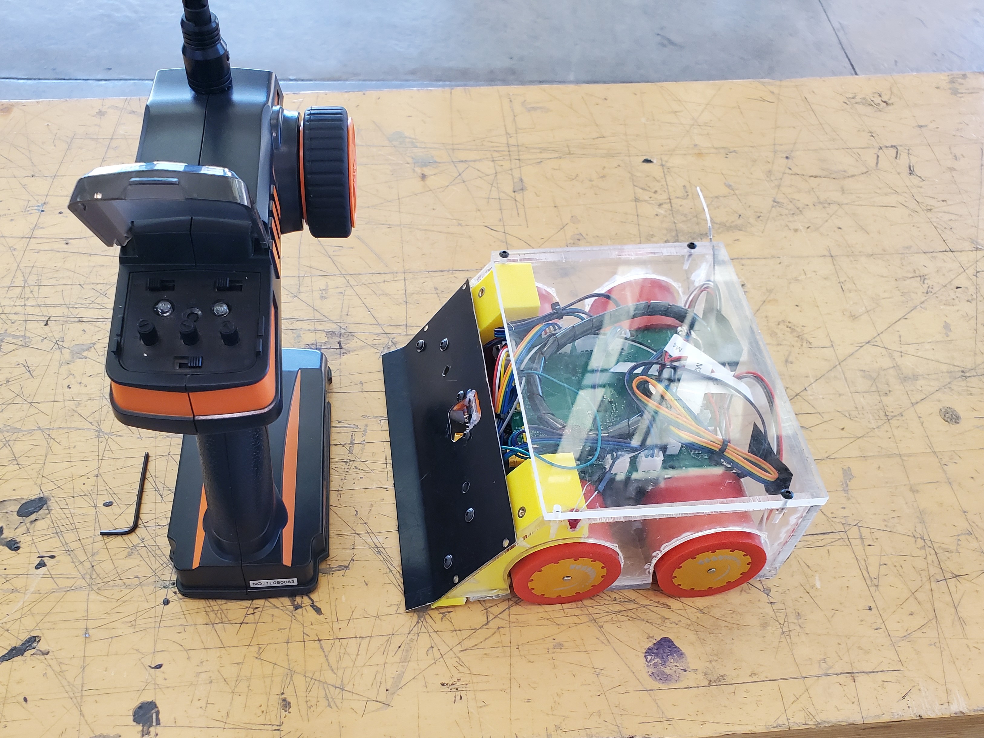
A sumo robot is built to autonomously push the other robot out of a ring on the floor. This robot was built by two teammates and I to compete in our class's competition. We designed and built the entire robot from scratch, including the PCB and code. While two of our sensors failed in combat due to EMI problems, the remaining sensors and hardware were robust enough to carry our team to first place among the five teams in the class.
As the first mobile robot I have built, I learned a lot about the convenience of wireless diagnostics and datalogging, as well as accessible reset and power switches.
Background
To prioritize reliability and clever code and strategy, our professor limited the size, weight, and power of our robots as shown in the table below.
| Mass | 1.5 kg |
|---|---|
| Bounding Box | 180mm x 180mm x 100mm |
| Battery Voltage | 12.6V (3S LiPo) |
| Battery Capacity | 17 W-h |
| Motor Size | Ø25mm x 32mm |
| Motor Quantity | 4 |
| Motor Power (combined) | 50W |
For safety, we were required to include a wireless 'deadman' switch to shut down the robot during a match in the case of a malfunction. The hardware for this feature would also be used to allow remote control of the robot for testing purposes. Finally, our professor required us to program a simple BMS to prevent the battery from over discharging.
Mechanical Design
Since traction was a huge part of the competition, we decided to place a motor on each of the four wheels. We also invested in the best urethane wheels we could find, which had a superior coefficient of friction to the standard silicone.
We built the chassis out of clear acrylic because we could laser cut it and we had some already. This turned out to be a mistake, as acrylic is very hard to work because it is so brittle. Regardless, being able to see into the robot was cool!
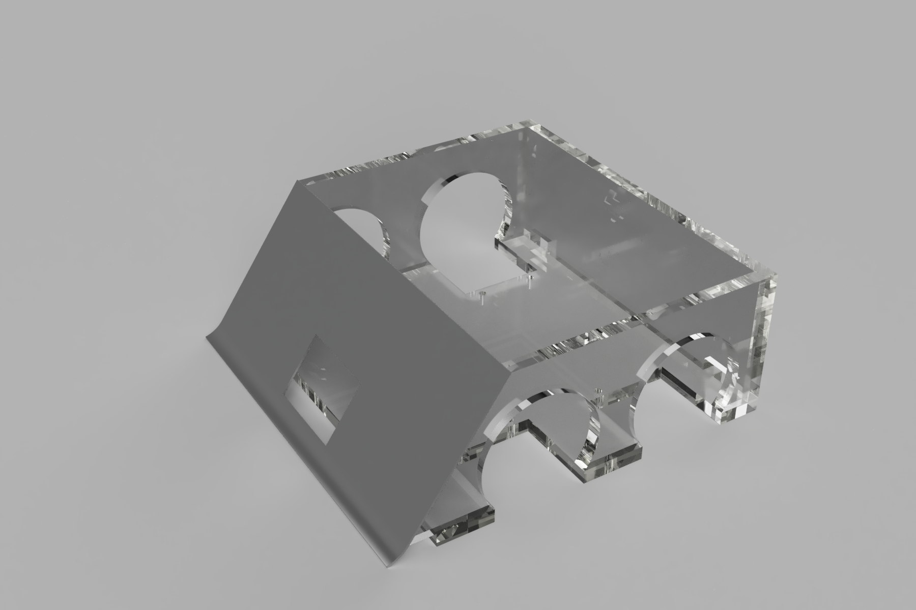
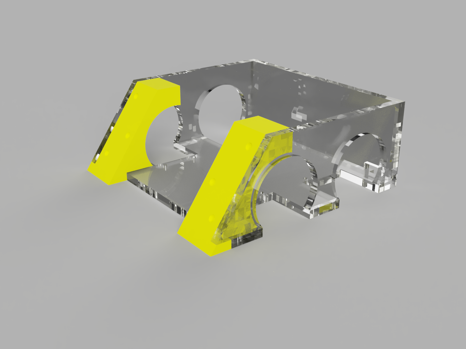
Like almost all sumo robots, we designed a scoop for the front. The goal of this component was to get underneath the opponent, removing weight from their tires and adding weight to our own. We made our scoop from sheet metal so it would be strong enough to take the hits and thin enough to get under the opponent. We also over drilled the mounting holes so we could adjust it to be as low to the ground as possible without scraping. At first, we planned to drill and tap the mount points into the acrylic frame. The acrylic proved too brittle for that, so we 3D printed corner blocks which would stiffen the frame and provide a mount point for the scoop. Threaded brass inserts would be melted into these blocks.
Given the diameter of our wheels, the weight of the robot, and the coefficient of static friction for urethane, we calculated each wheel being able to withstand 92.36 oz-in of torque before slipping. Using this value, we selected a motor that could produce 100 oz-in. The gearing on these motors made them a little slower than the competition, but the greater torque proved more valuable.
Electrical Design
The PCB is powered by a 3S Li-ion battery (12 V), which feeds through an automotive fuse and a MOSFET wired to provide reverse-polarity protection.
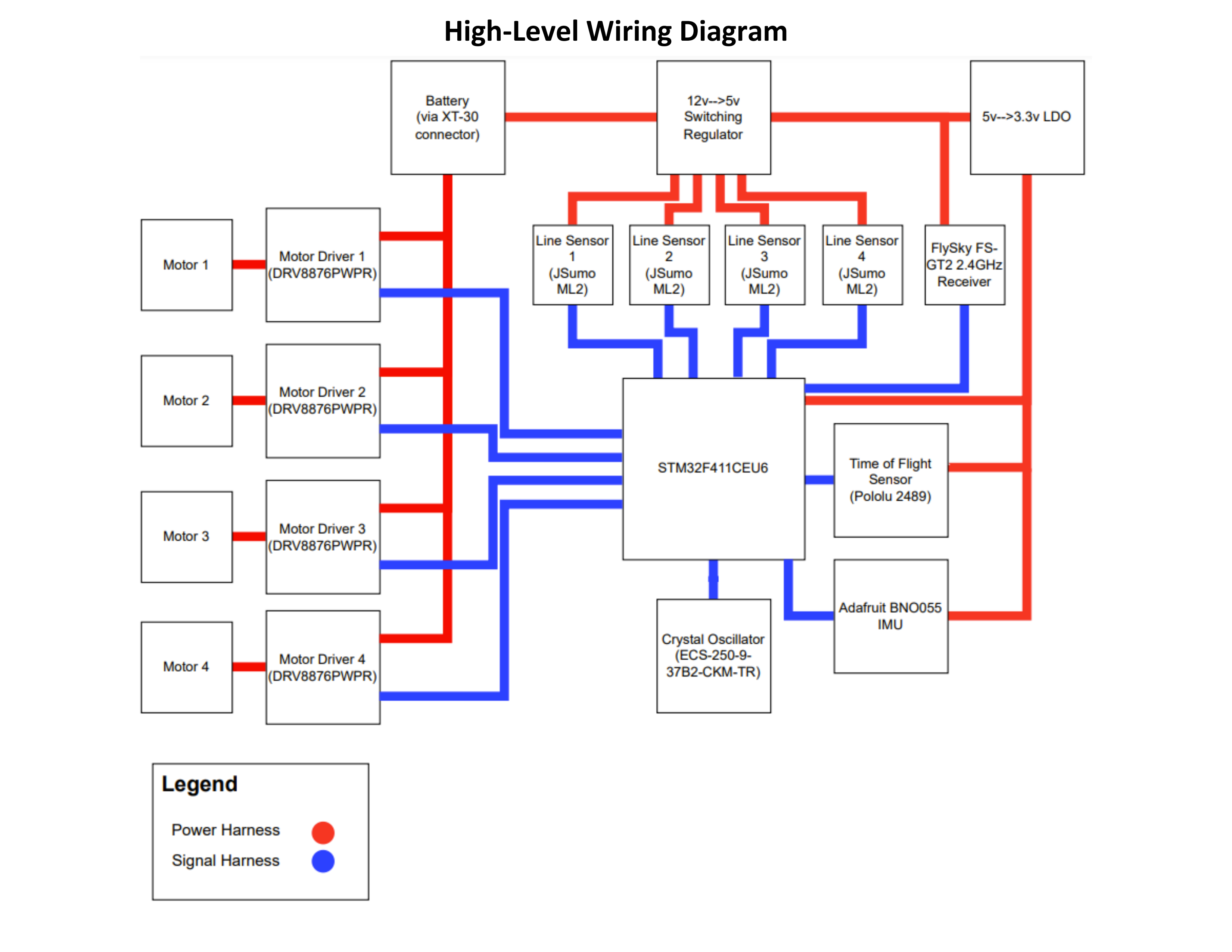
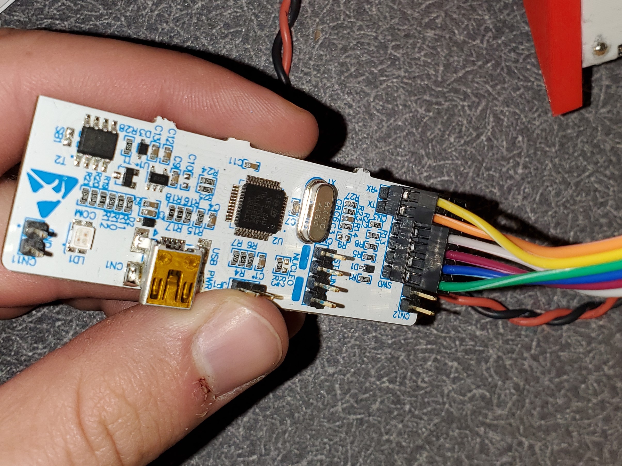
The microcontroller is an STM32F411CEU6. For simplicity and commonality, this was specified by our professor. We selected supporting capacitors and oscillators per datasheet recommendations. For simplicity, we omitted a USB port and made our serial and programming connection via an external FTDI module, the ST-link.
In case of future modifications or repairs, we included pin headers for each of the voltage rails, as well as any unused GPIO pins. We ended up using one of these pins to control a status LED which illuminated when a low-voltage shutdown was active.
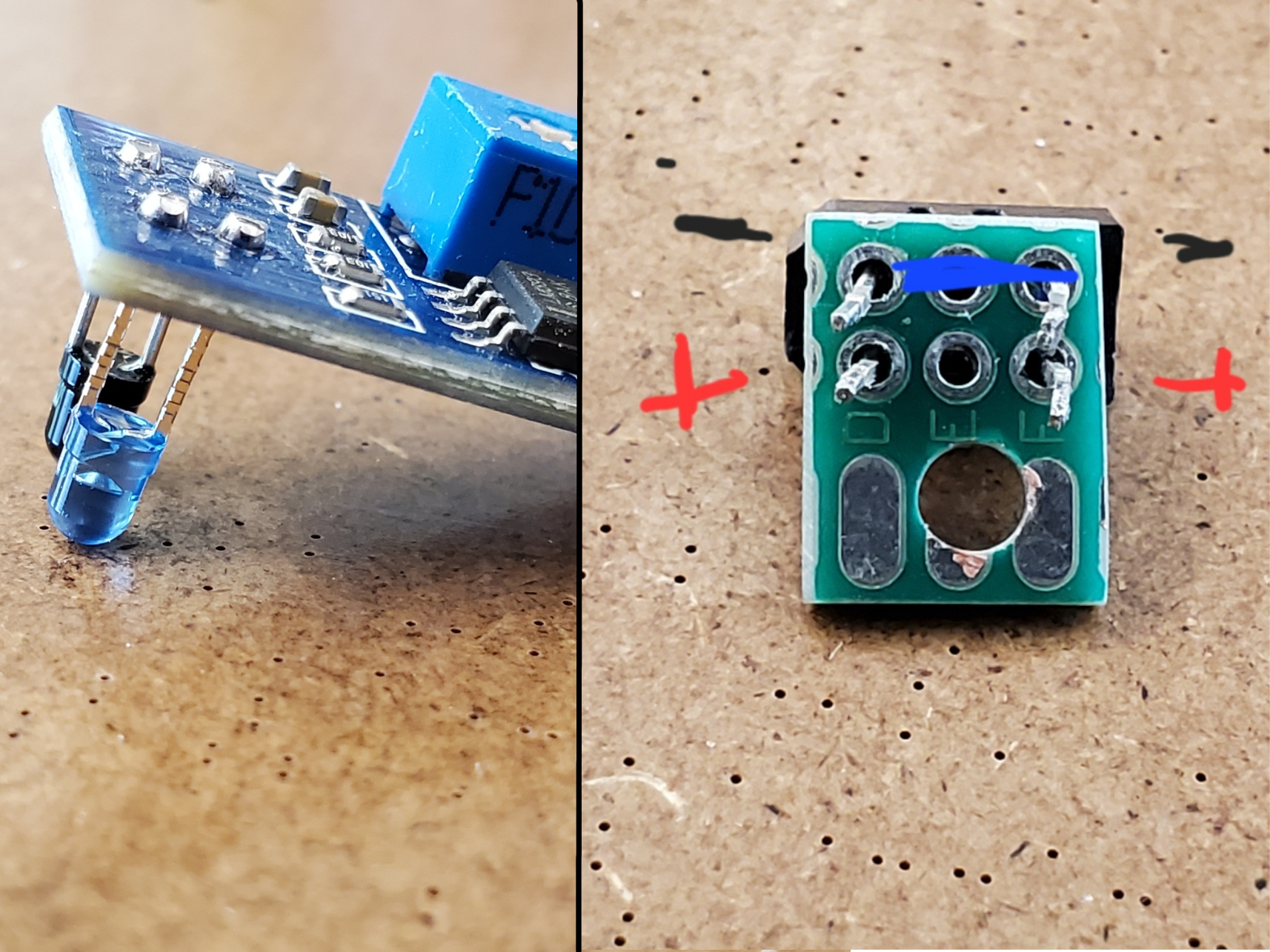
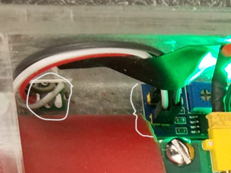
For sensors, we started with four IR line sensors, one on each corner. These detect if the robot is about to exit the ring. Due to shipping delays with our preferred sensor, we ended up using a different larger sensor from another team. To make them fit in the rear of the robot, we had to resolder the IR emitter/detector to a smaller piece of PCB, connecting it to the processing unit with short wires.
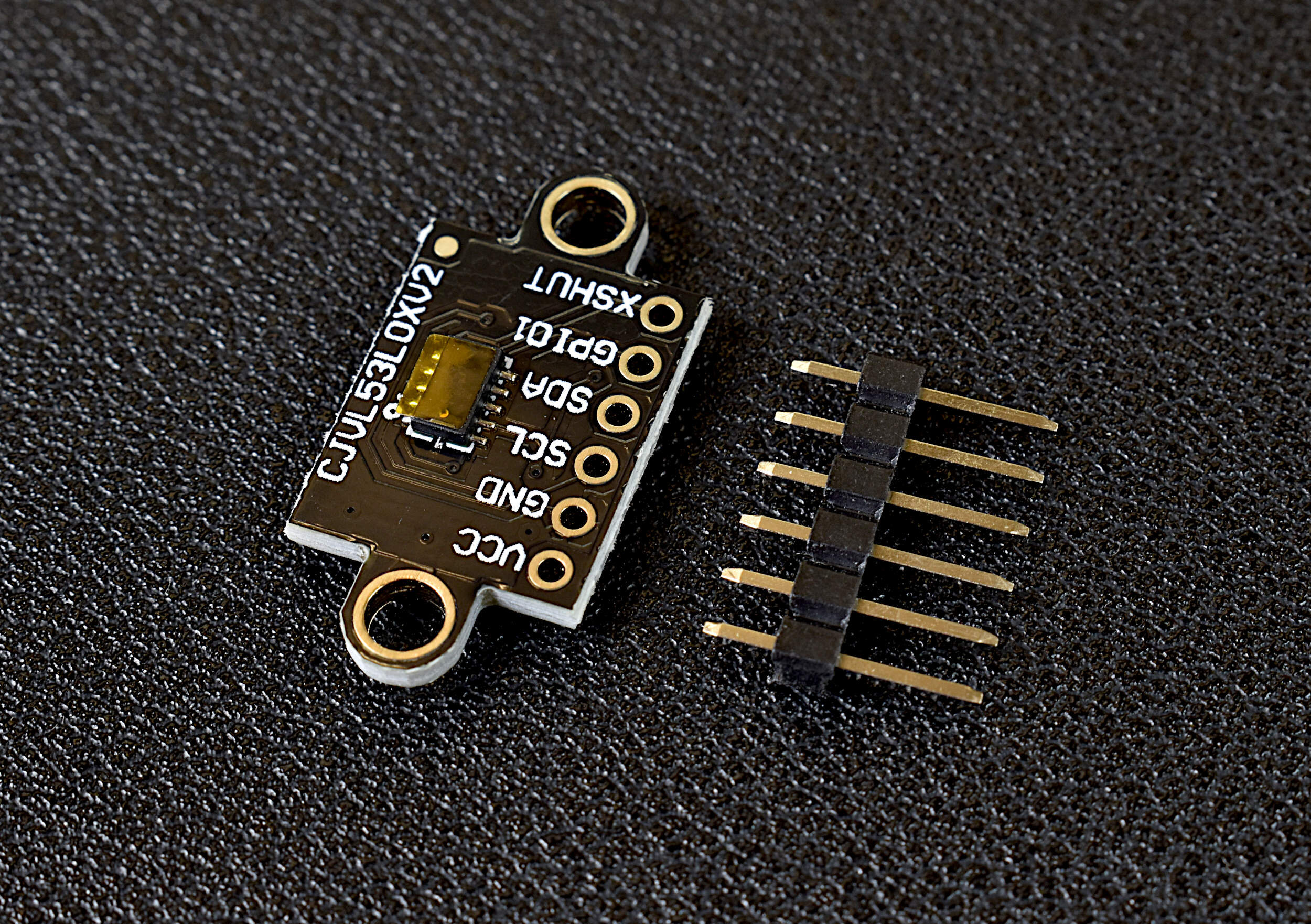
Mounted to the front scoop with a 3D printed bracket, we had a Time-of-Flight range sensor to detect the opponent at a distance. Time-of-Flight sensors are not susceptible to sunlight like IR sensors, or to interference like ultrasonic sensors. Initially, we selected a VL6180X, but at the last minute, we switched to a VL53L0X for the improved range.
Attached to the chassis was a BNO055 IMU from Adafruit. The idea behind this sensor was to detect impacts on the robot. That way, if an opponent crashed into us, we would know from what direction and be able to react accordingly.
Fabrication
After laying out the schematic, it was time to route the PCB using Fusion 360 (formerly Eagle). We used a 4-layer design because of our multiple voltage rails and to allow larger power and ground planes for the high-current 12V rail.
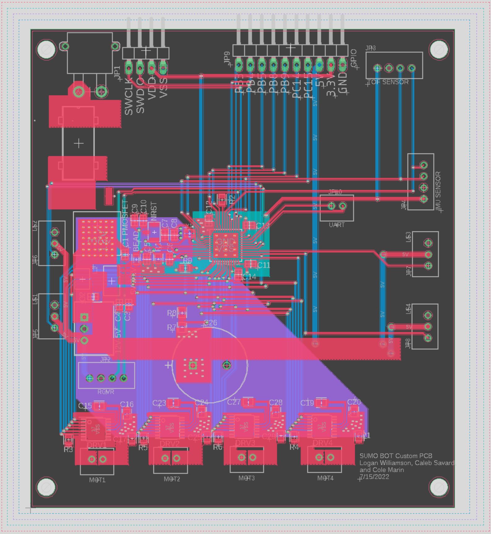
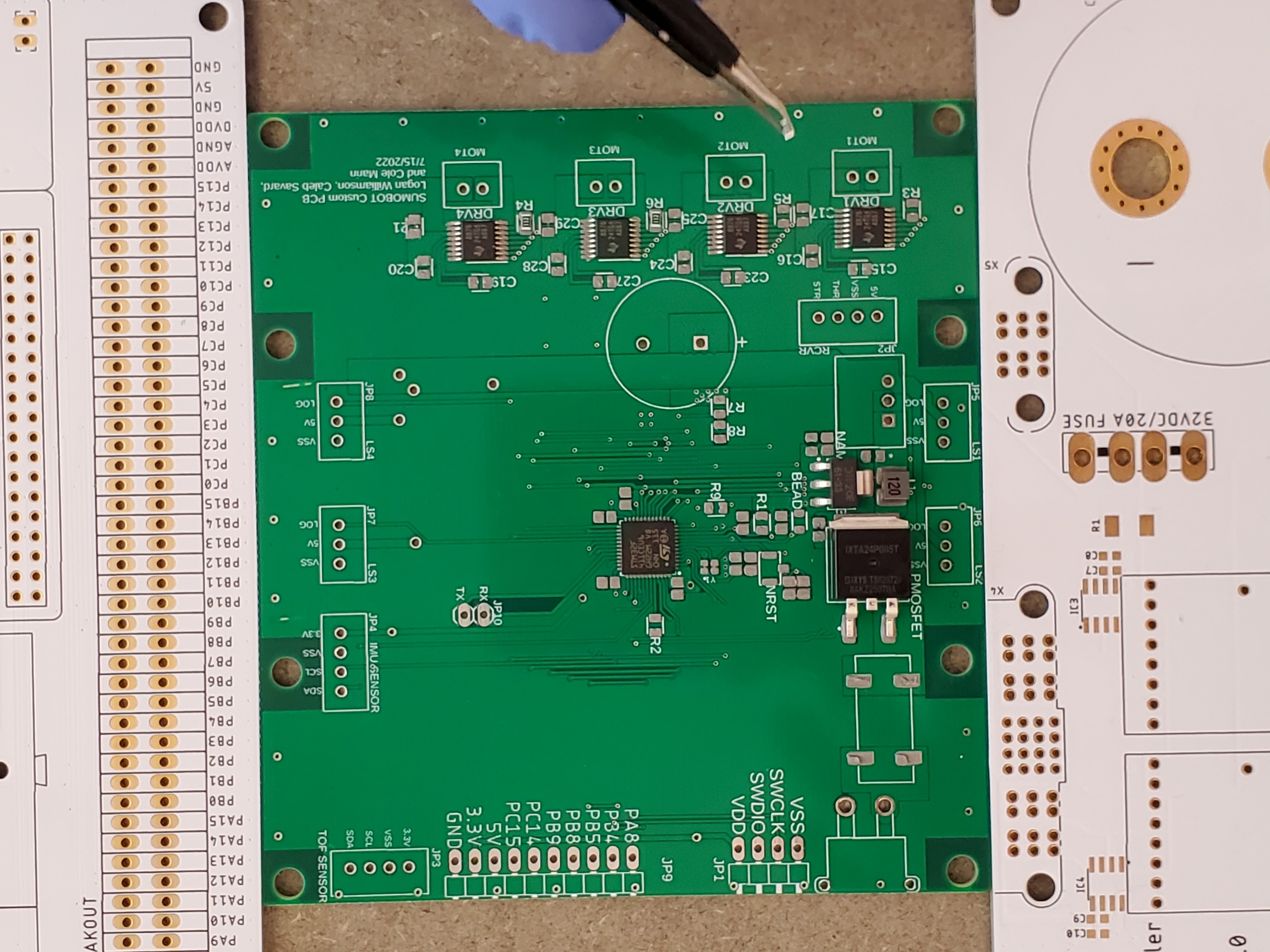
We had the PCB manufactured through JLCPCB and it arrived with a solder mask included. After laying down the solder paste and placing the components, we used a hot plate to reflow the board. I did a few minor touch-ups with a soldering iron and the board was operational.
Mechanically we had to make a few modifications. First was the 3D printed scoop mount mentioned previously. We also noticed that we would have to lower the wheels to prevent the bottom from scraping on the ground. Logan milled a little off the bottom of the motor mounts to make this happen.
Software
All the code for the project was written in C++ using ST's CUBE IDE. This software automatically generates code for hardware setup like pin configurations, timers, and callbacks while still allowing direct access to these features. Our main loop consists of a few tasks in a cooperative multitasking structure, as well as a few other features. The main Finite State Machine which handles decision-making is shown below.
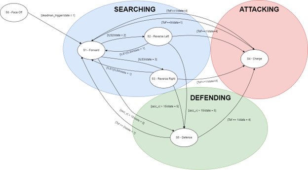
While in the Searching state, the robot would drive forward until one of the front line sensors detected the edge of the arena. Then it would make a reversing turn until the rear line sensor detected the edge and drive across the arena again. This way, it crisscrossed the arena in a star patten to find its opponent.
The attack state would apply more power to the motors and would keep doing so until the Time-of-flight sensor no longer detected the opponent in front of it. The defense state would be triggered by an impact and would consist of an evasive maneuver.
Drivers were written for each of the components. APIs were available for the IMU and the Time-of-flight sensor, but they were designed for Arduino and had to be modified to work with the CUBE IDE. I was in charge of the Time-of-flight driver, which I ended up building twice since we switched sensors at the last minute. That was a long day in the lab…
Results
As we began testing our robot we noticed a few problems with our IMU and Time-of-flight sensor. First, the IMU signal for the abrupt halt at the edge of the arena was stronger than the signal from a real collision. We would need more code to ignore acceleration induced by our own movements, and we didn't have time for that. We could have still used it to detect T-bone collisions if it weren't for our second problem. Even though both sensors worked well on the bench, they rarely worked in the ring. Once the robot started moving, we got communication errors with these sensors, so we eventually suspected a problem with the I2C bus. Other teams were having similar problems and we thought EMI from spinning motors was causing it. On further research, we learned that I2C is very sensitive to such interference and is not recommended for this application.
Lacking time to fix the problem, we opted to drop the attack and defense states and compete only in the searching state. The robot was limited on power and blind, but its robust motors and tires and low front scoop were enough to succeed. We placed first out of 5 teams.
Contributers

Logan Williamson


Cole Marin
Cal Poly