


Skills Showcased
This robot was the final project for my second Mechatronics class. It draws any image with a pen, and can even write letters input by the user. My partner and I designed and built all the hardware, and wrote all the code. Since the software was written in microPython (a version of python designed for microcontrollers), no libraries were available, so we got the opportunity to write everything from the ground up.
Background
The assignment was to create a plotter robot which could draw images from an uploaded .hpgl file. The catch was that cartesian coordinates were not allowed. This made the kinematics more challenging and resulted in more interesting robots. We were required to use stepper motors for the two primary actuators. Our professor provided an STM Nucleo microcontroller and a custom stepper motor driver board, as well as a variety of salvaged parts.
Mechanical Design
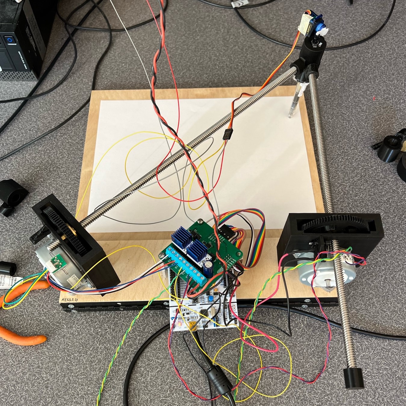
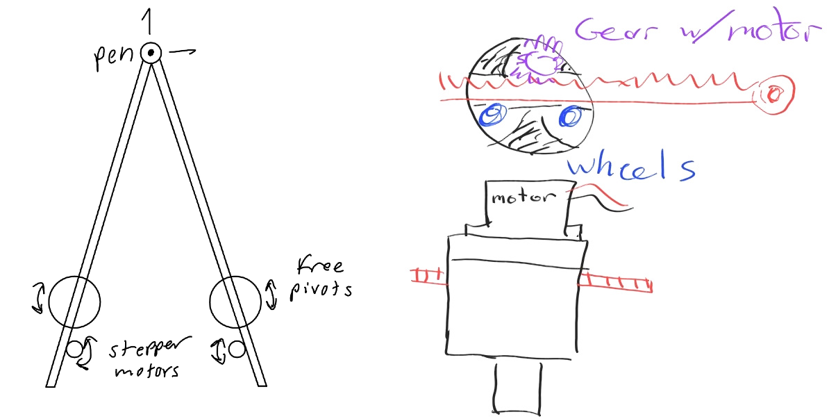
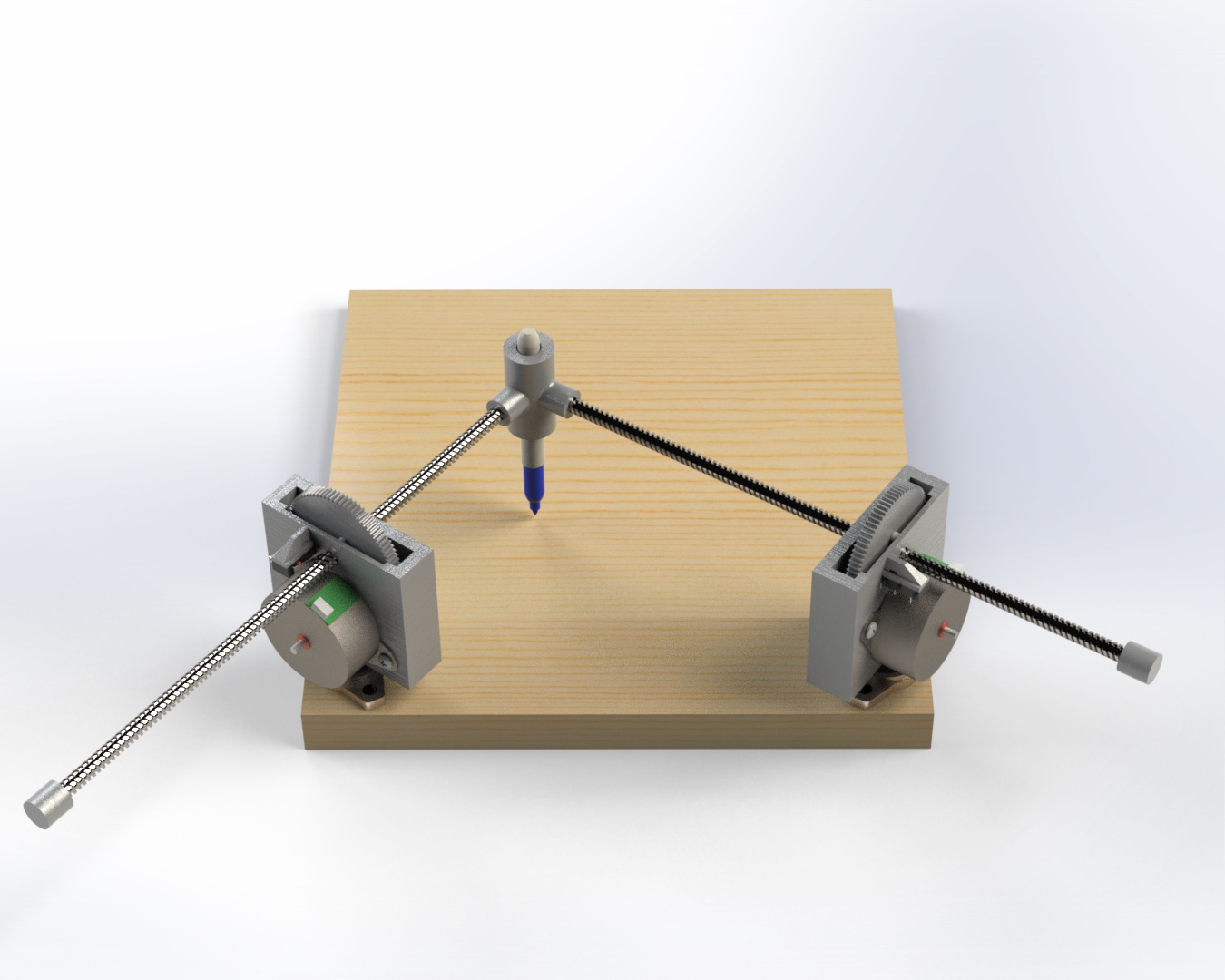
Our robot is basically a triangle with two sides of variable length. Changing the length of these sides positions the pen at the intersection. We chose this layout simply because we though it would look neat.
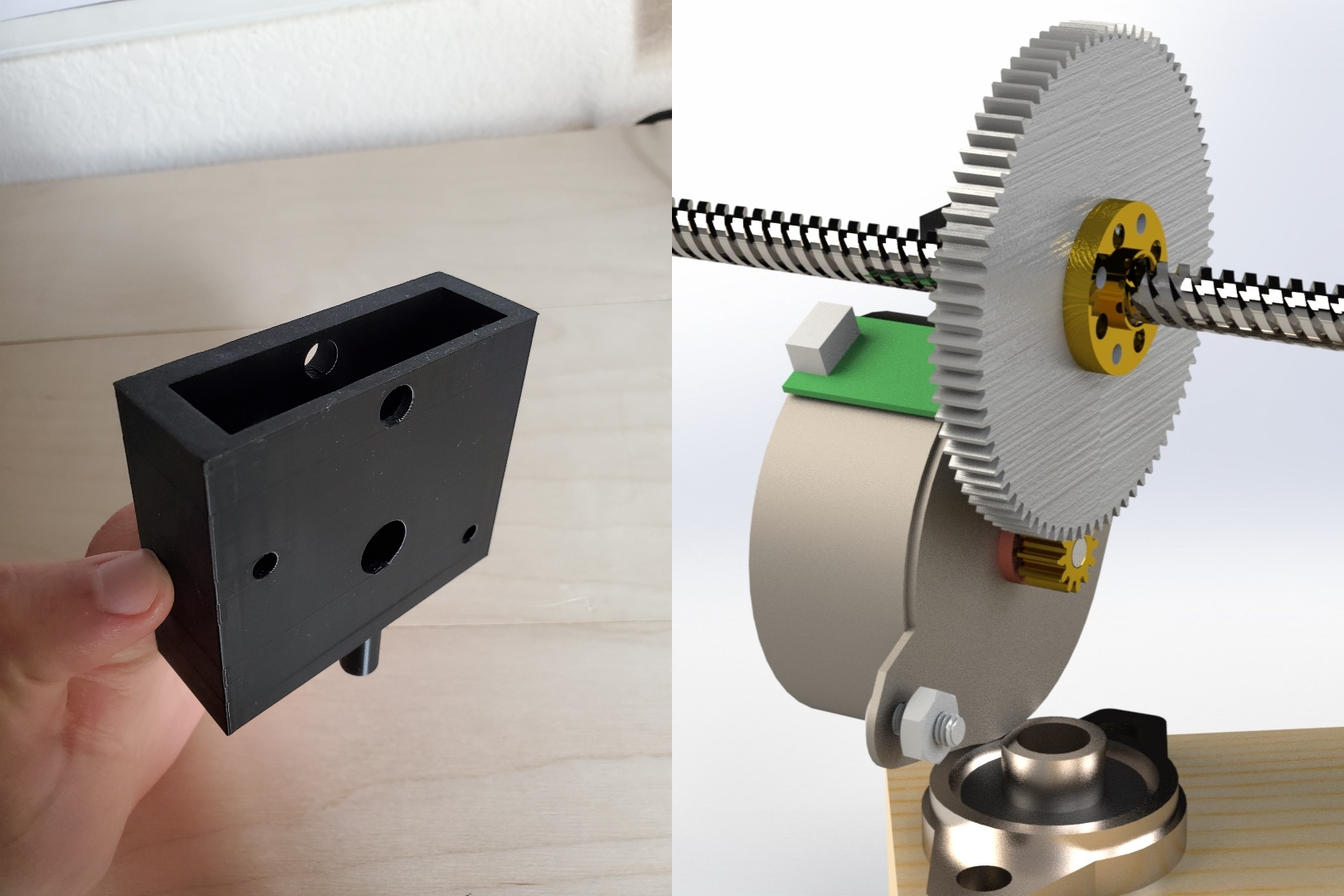
To accurately control the length of the sides, we iterated through a number of ideas to develop a leadscrew design where the nut is rotated around a static shaft. The advantages of this system over a smooth friction-driven shaft or a rack-and-pinion is that the shaft cannot slip relative to motor rotation and the significant speed reduction increases positional accuracy.
I designed a single unit to be 3D printed which would house each motor and leadscrew assembly. One interesting feature of this module is recesses for the nuts, allowing the motor screws to be tightened without having to fit a wrench over the nut. I also included mounting points for limit switches, but we ran out of time to implement these fully.
Initially we planned to use an electromagnetic solenoid or a DC gearmotor to drive the pen up or down. These ideas failed and we were forced by our deadline to use a simple hobby-grade servo. The rest of the design was fairly simple. We modeled the whole system in SolidWorks to ensure it could move like we envisioned.
Analysis
Given the non-linear nature of our system, it was impossible to derive an equation which would output motor angles for desired X-Y positions of the pen. Fortunately the reverse (called the 'forward kinematics') was possible. Using the geometry of the system, I derived the following equation.
$$ \bar{f} = \begin{bmatrix} f_x \\ f_y \end{bmatrix} = \begin{bmatrix} k(\theta_2^2 - \theta_1^2) + \frac{l}{2} \\ \sqrt{k\theta_2^2 - [\frac{k(\theta_2^2 - \theta_1^2) + l^2}{2l}]} \end{bmatrix} \text{where } k = (\frac{N_A}{P N_B})^2$$This would be used later to iteratively approach a solution for the required motor angles. Full calculations can be found on the project website linked at the bottom of this page. To ensure that this control method would work before building all the hardware, we wrote a Google Collab report to test it. The result was the animated .gif shown above.
Fabrication
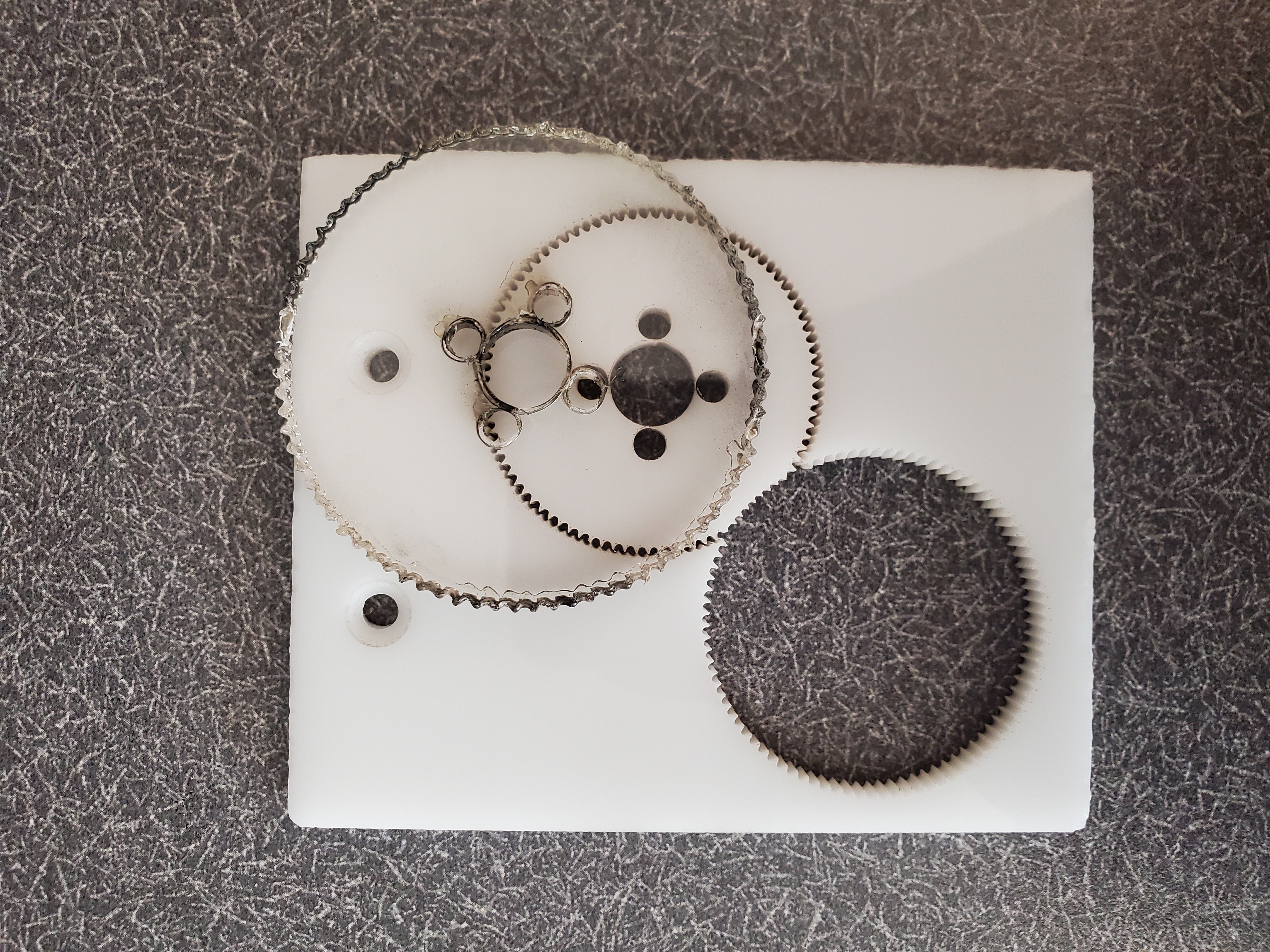
Most parts were 3D printed due to the process's broad capabilities and fast turnaround time. We tried laser cutting the gears out of acrylic, but the melting effect of the laser made it impossible to get the detail we needed. This may have been a mistake in our laser settings, but we decided to just 3D print the gear too.
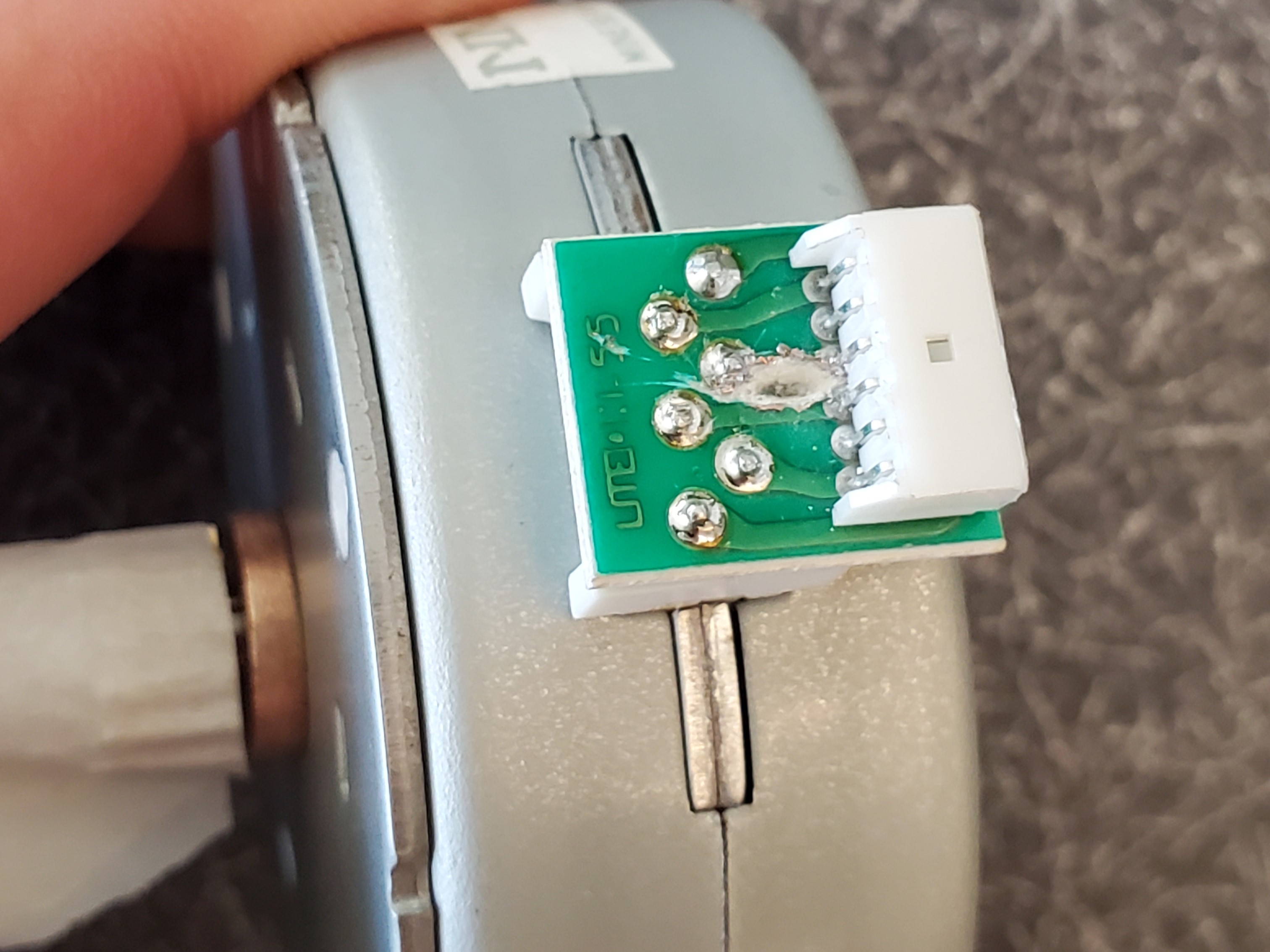
The stepper motors we used were refurbished or surplus units available for free in the lab. They appeared to be 5- or 6-wire stepper motors, so we had to modify them to work with our 4-wire driver. We did this by desoldering the small PCB which the motor coils were wired to, cutting a trace or two on the surface, and soldering it back in place.
The mounting holes on our leadscrew nuts were so close to the center that the heads of our mounting screws were interfering with the center part of the nut. To remedy this, we drilled and tapped four more holes for smaller screws slightly further from the center.
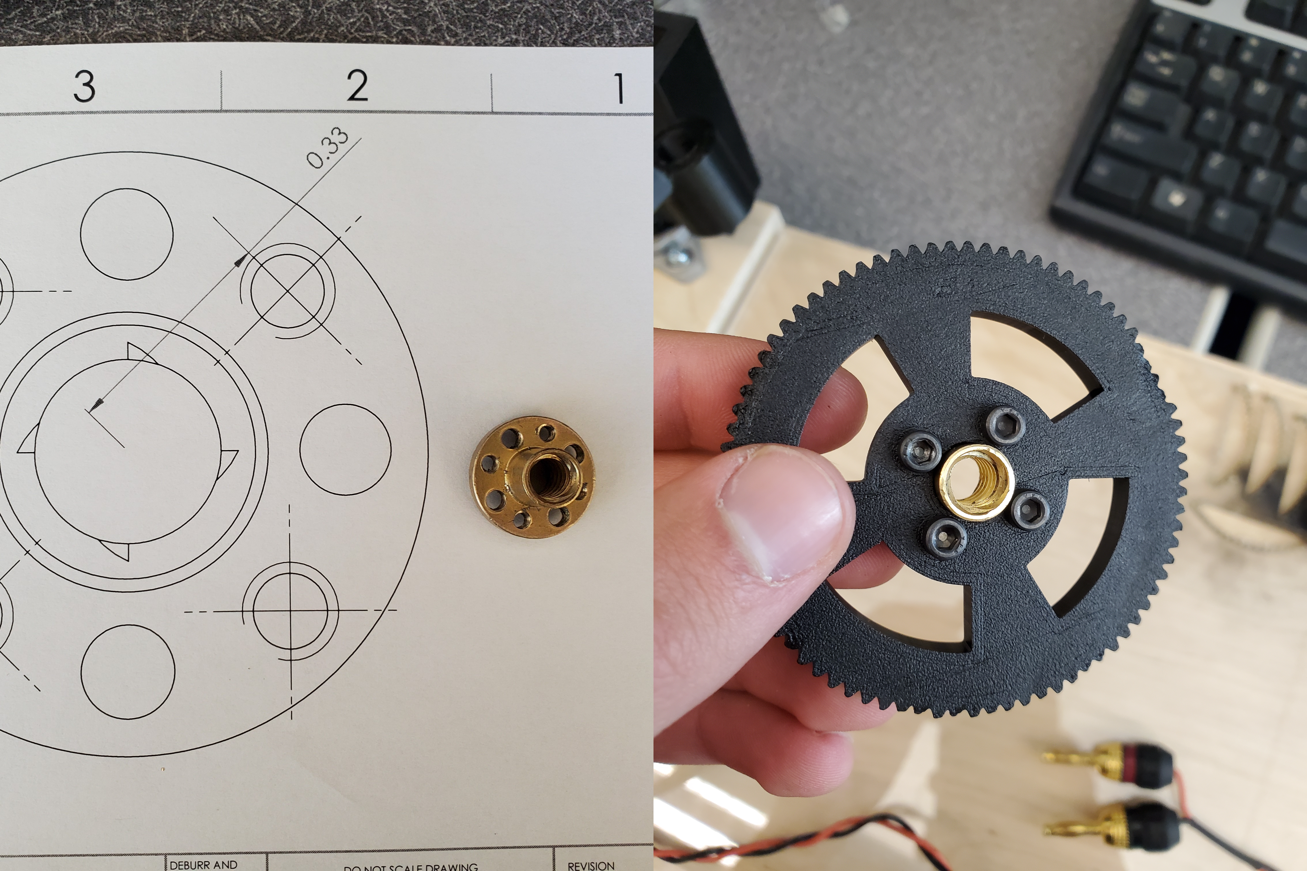
To make this easier, I printed out a 1:1 scale drawing of the hole locations, cut out the center bore from the paper and slid the drawing onto the physical nut. Then I could mark the hole locations directly onto the part with a center punch.
Software
All our software was written using microPython, an adaptation of python for microcontrollers. While it can be slower than C or C++, the ease of python programming and the access to standard python libraries made it well suited to this project. Our code used a cooperative multitasking structure, where a number of short, blocking tasks are run at frequent intervals.
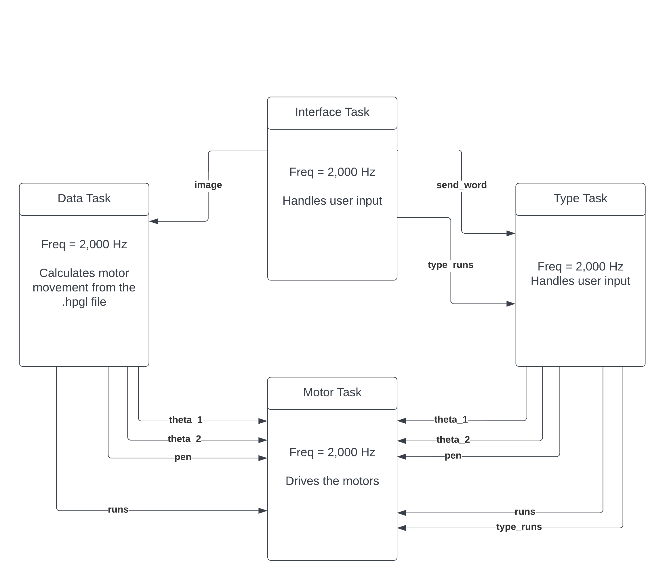
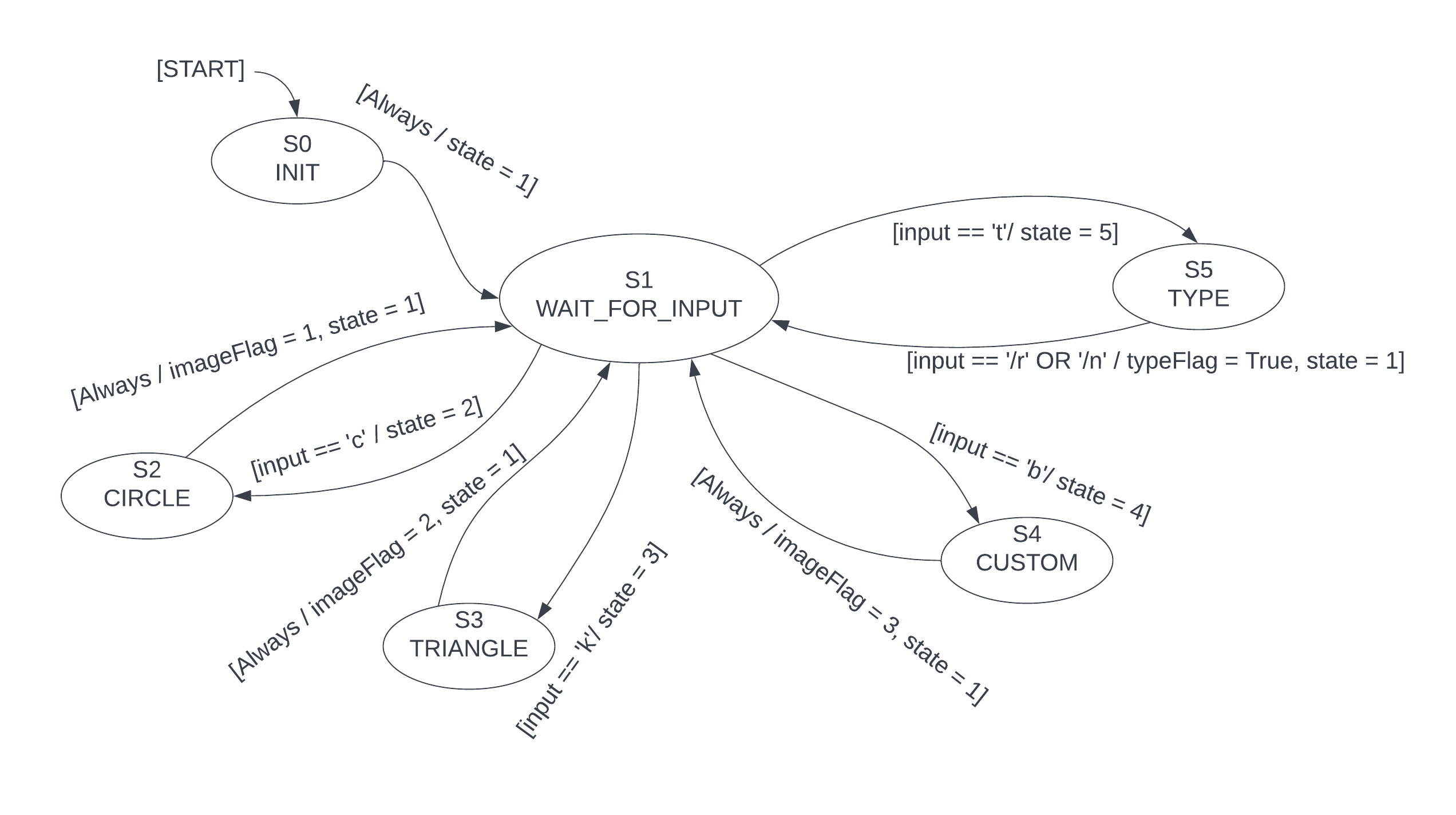
The Interface Task handles the serial UI, taking commands from the user, printing feedback, and triggering either the Data Task or the Type Task, depending on the input. The state diagram below shows that a state exists for each of the drawing options which sends the appropriate data to the appropriate task.
The Data Task takes an .hpgl file representing the selected image, parses out the relevant X-Y points and outputs a set of motor angles to the Motor Task. These motor angles are calculated using the Newton-Raphson algorithm, which iterates through the forward kinematic equation from the Analysis section to find a solution for the desired motor angles for a given set of X-Y coordinates.
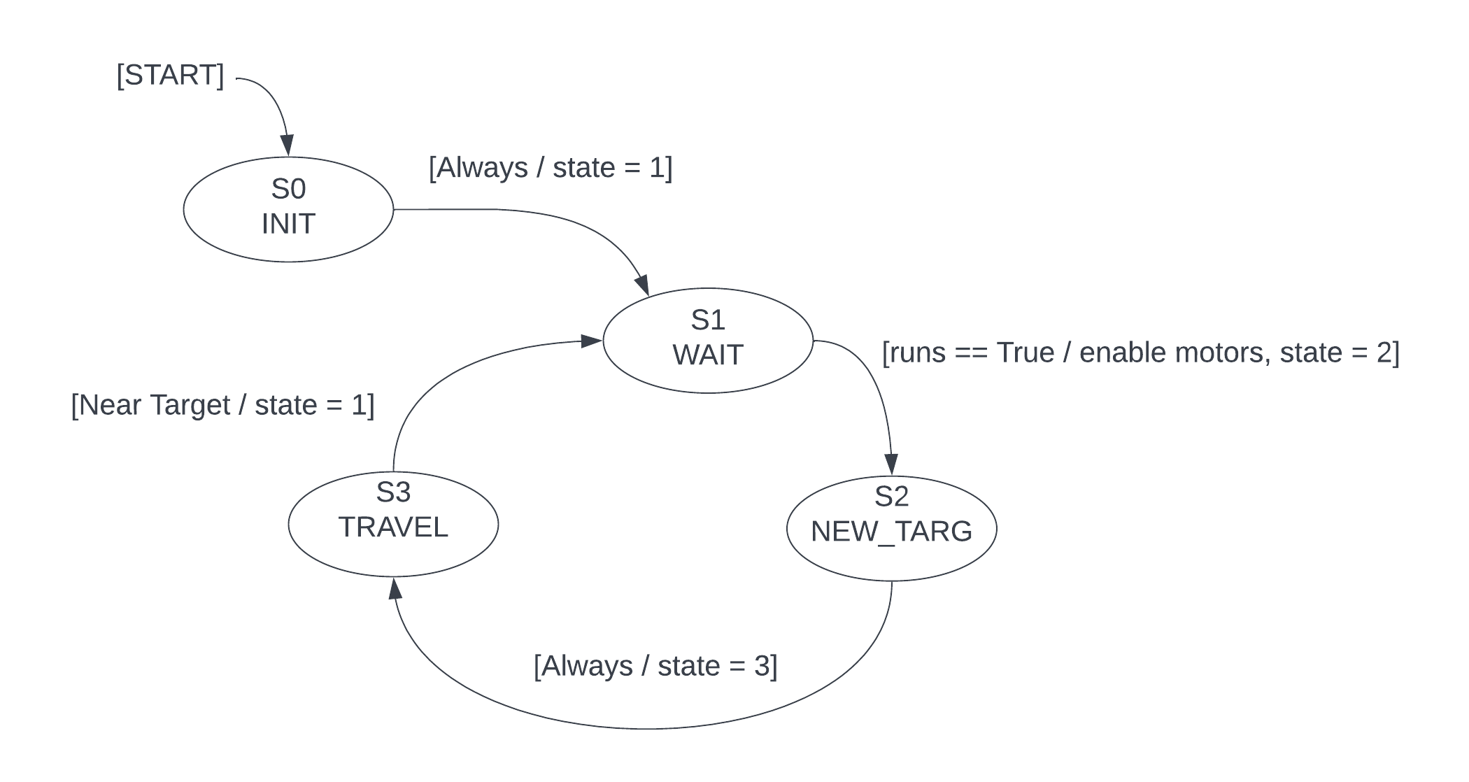
The Motor Task drives the motors to the target angles calculated by the Data Task. In the state diagram below, the three states of the Motor Task are shown. WAIT immediately forwards to the next state as long as the run variable is true. This allows the process to be stopped at any time by resetting the run variable. NEW_TARG assigns the next target angle to each motor from the list produced by Data Task. TRAVEL waits until both motors have neared their targets before starting the cycle over again.
The Type Task is essentially the same as the data task, except that it takes a string input from the Interface Task and processes .hpgl files corresponding to the letters in the string.
The hardware is controlled via a few classes, which handle all the low-level driver settings and controls. Details on these classes can be found on the project website linked at the bottom of this page.
Results
Below are some samples of what the robot was able to draw, compared to the vector drawing it was given.
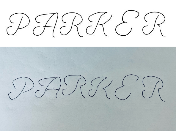
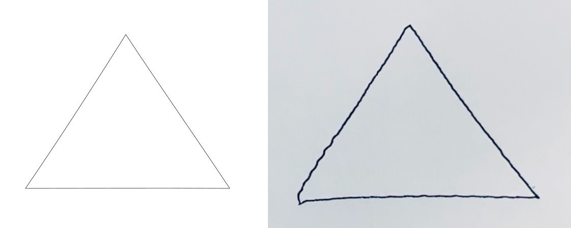
Clearly the robot is able to reproduce these shapes, and watching it do so if entertaining, even if it is a bit slow. Some jagged lines are visible on the drawing, which are due to the motors moving from point to point at full speed. If one motor reaches its target angle first, it simply stops and waits for the other. This effect is minimized when the lead screws are symmetrically extended as the motors must travel more similar distances. This could be improved by normalizing each motor's speed to the distance it must travel, ensuring that both motors reach their target at the same time. A sort of 'curve fit' could also be applied to the list of motor angles, which could have a smoothing effect on lower resolution .hpgl files.
My favorite part about this project was the opportunity to develop both the hardware and software from scratch. I like working with both and seeing how they influence each other, and its not common to get a class which doesn't focus on one or the other.
Contributers

Parker Tenney

Cal Poly