


Skills Showcased
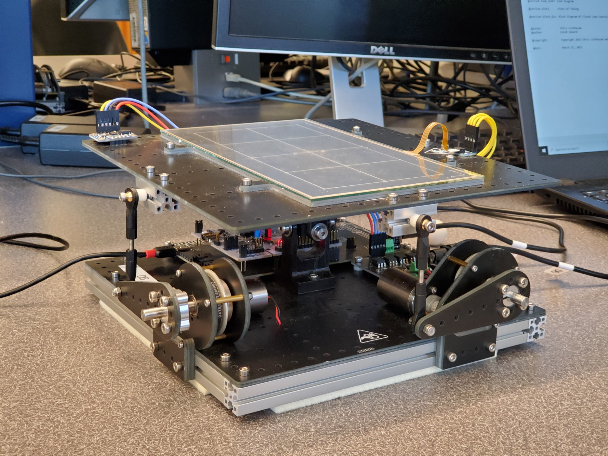
This robot balances a ball on a tilting resistive touch panel. The hardware was prebuilt since, as the term project for my first Mechatronics class, the emphasis was on the software. The project involved sensor and motor control, serial communication, kinetic and kinematic analysis, and control loop algorithms. Our longest balance time was 24 seconds, which we believed to be limited by hardware problems.
Background
The software for this project was written in microPython, a version of Python adapted for the limited resources of microcontrollers. The microcontroller for this project was an STM32 Nucleo, loaded with the microPython firmware and mounted on a 'Shoe of Brian' PCB to allow for easier access to the serial port.
The tilt table was actuated by two DC motors (one for each axis), connected to lever arms with belts. This setup is not quite linear, but its close enough for this project. Mounted on the tilt table was a 4-wire resistive touch panel and a BNO055 IMU. These sensors were used to locate the ball on the table, and read the orientation of the table.
Functionality and Features
The main functions of the device are printed to the serial port during initialization.
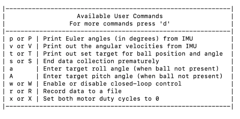
Aside from the balancing feature (initiated by pressing W and placing the ball on the panel), data from the sensors could be printed to serial, motors could be manually controlled, and a datalog could be made.
We also implemented some developer commands allowing the user to edit PID control values and clear calibration constants for testing purposes.
Not shown in the menu is the calibration process, which runs on startup unless values have already been saved to a file on the Nucleo's memory. This process ensures that values from the touch panel and IMU are accurate.
Tasks
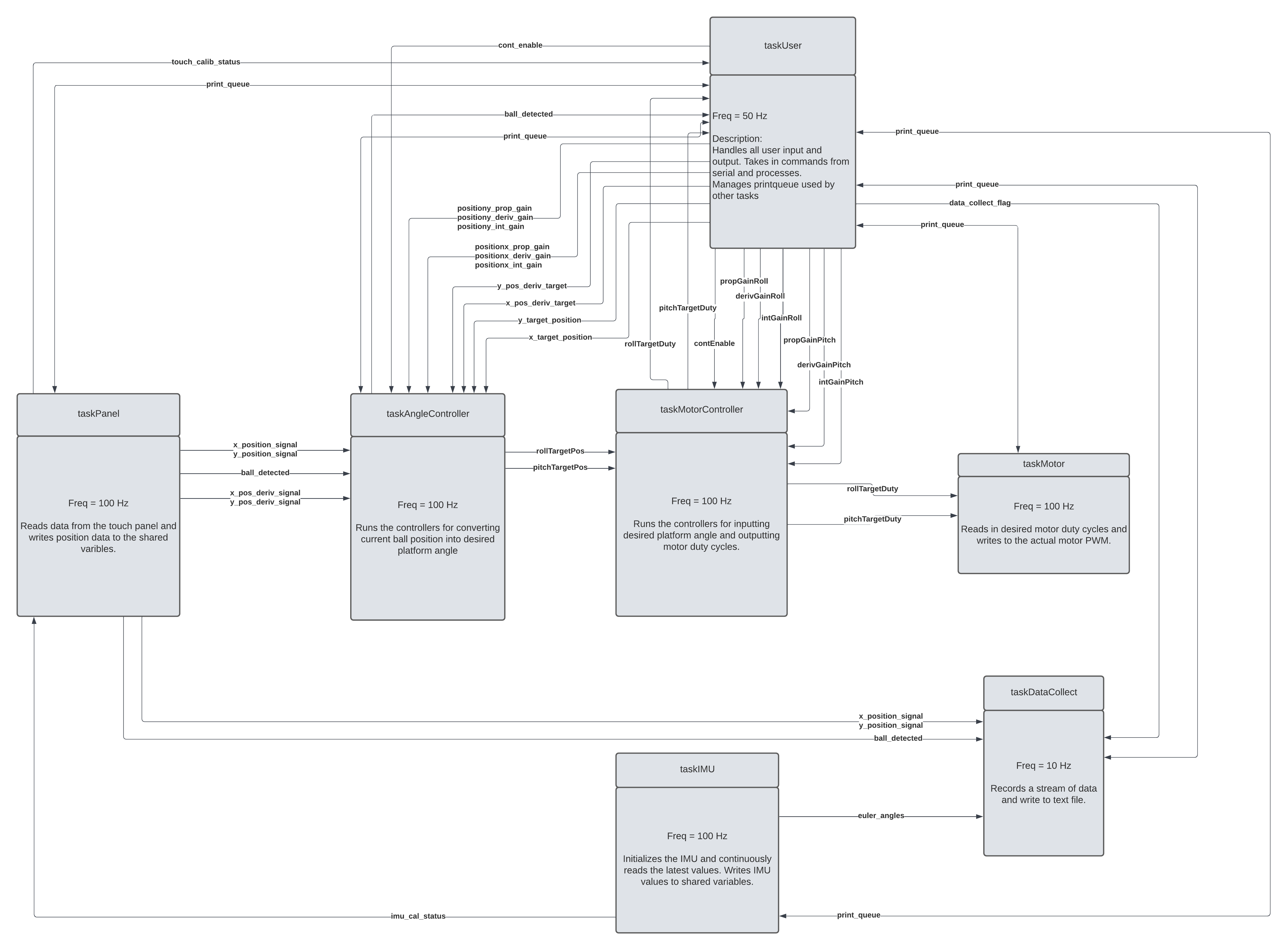
The robot runs on a cooperative multitasking system, where a number of tasks quickly repeat one after another to mimic true multitasking. In this sort of system, it is critical that each task is short. Any task which takes too long can hold up, or block, the entire system.
The most visible of these tasks is the taskUser>. It handles the sensor initialization and calibration, user menu display, user input, and serial printing. It is taskUser which commands the other tasks to respond based on user input.
Both sensors have their own dedicated tasks (taskIMU and taskPanel) which handle calibration which commanded by the User Task, and otherwise collect data from the sensors and supply it to other tasks.
The hardware control system consists of three tasks. taskAngleController takes the sensor input and uses a PID control algorithm to output a target angle for the tilt table. taskMotorController then takes these target angles and specifies a duty cycle for each motor. Finally, taskMotors writes these duty cycles to the motor driver hardware.
The last task in the system is taskDataCollect, which logs the table angle and ball position for a certain duration, then writes the data to a .txt file on the Nucleo's memory.
Simulation
In preparation for this assignment, and to better understand the kinematics of the system, we were tasked with creating a 2D simulation in MATLAB which could predict the motion of the system given the location and velocity of the ball and the platform, as well as the torque input. The full simulation code is linked at the bottom of this page.
To learn about the tuning process and eliminate some of the inconsistencies of real life, I created a Simulink PID control system that could interact with the simulation we had already written.
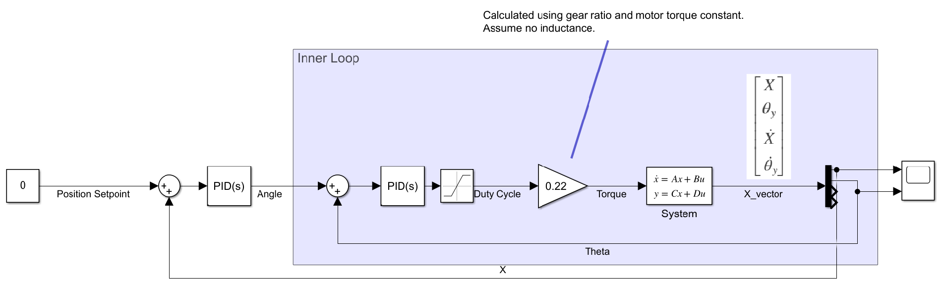
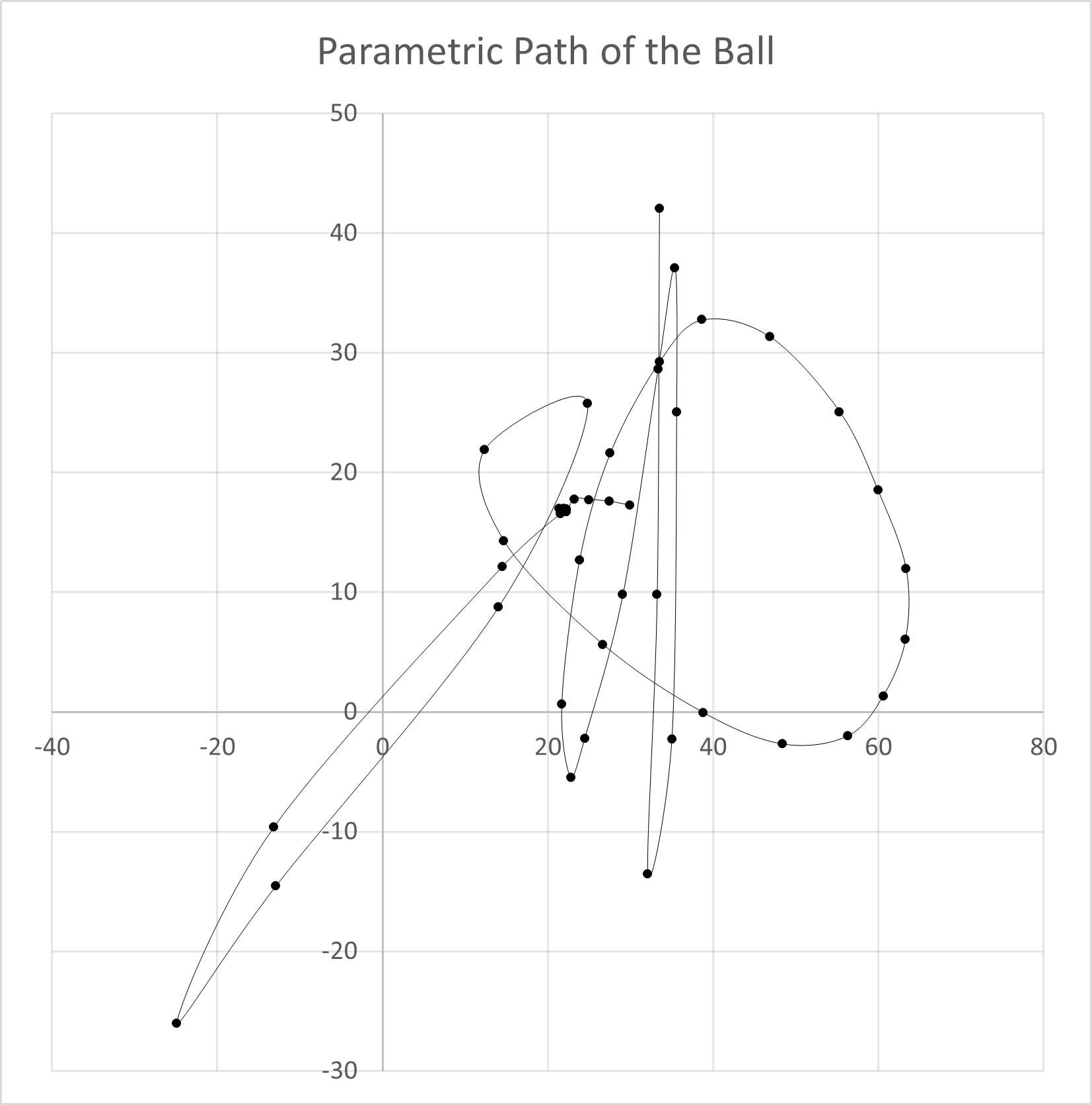
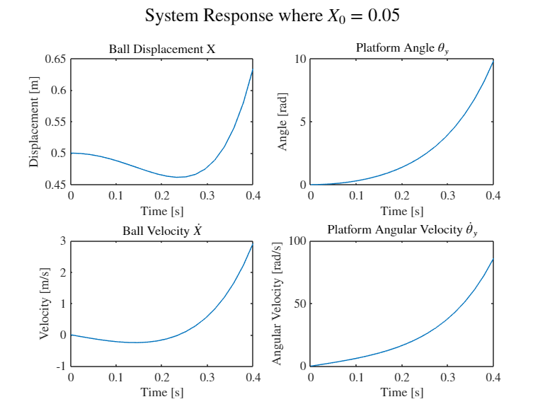
My intent was to quickly tune the virtual system, where tests could happen instantly instead of waiting for the system to stabilize, then transfer those PID values to the real robot to give us a good place to start. The following response graph shows system stability.

Unfortunately, the physical values used in our system simulation were not representative of the real system, which meant the PID values we developed virtually were not relevant to the physical control system. Additionally, the simulation did not account for hardware problems, such as motor torque limits or belt slipping. In the end, it was useful to get practice tuning an ideal system, but it did not give us good values to start tuning the real machine.
Results and Conclusion
My favorite part about this project was getting to learn to write code that actually interfaced with hardware. I had dabbled in Arduino blinking light sketches and was proficient in MATLAB, but this was the first time I saw what I wrote making a physical object move, which was really exciting for me! I also appreciated having a teacher (and a teammate) to answer questions and point me in the right direction. This was the class that got me past the bar of entry for DIY mechatronics and enabled me to continue to learn on my own with the help of google.
Our longest balance time was 24 seconds, which was among the highest in the class. We thought the system could balance longer if we had more time to tune and make changes to the hardware, but I'm pretty happy with the results we achieved.
Contributers

Chris Linthacum

Cal Poly